
 5秒后页面跳转

| 是否Rohs认证: | 符合 | 生命周期: | End Of Life |
| 包装说明: | , | Reach Compliance Code: | compliant |
| ECCN代码: | EAR99 | Factory Lead Time: | 26 weeks |
| 风险等级: | 5.34 | 配置: | Single |
| 最大漏极电流 (Abs) (ID): | 100 A | FET 技术: | METAL-OXIDE SEMICONDUCTOR |
| 湿度敏感等级: | 1 | 最高工作温度: | 175 °C |
| 峰值回流温度(摄氏度): | NOT SPECIFIED | 极性/信道类型: | N-CHANNEL |
| 最大功率耗散 (Abs): | 163 W | 子类别: | FET General Purpose Power |
| 表面贴装: | NO | 处于峰值回流温度下的最长时间: | NOT SPECIFIED |
| Base Number Matches: | 1 |
| 型号 | 品牌 | 获取价格 | 描述 | 数据表 |
| AUIRFU9024N | INFINEON |
获取价格 |
Power Field-Effect Transistor, 11A I(D), 55V, 0.175ohm, 1-Element, P-Channel, Silicon, Met |

|
| AUIRFZ24NL | INFINEON |
获取价格 |
Advanced Planar Technology Low On-Resistance |
|
| AUIRFZ24NS | INFINEON |
获取价格 |
Advanced Planar Technology Low On-Resistance |
|
| AUIRFZ24NSTRL | INFINEON |
获取价格 |
Advanced Planar Technology Low On-Resistance |
|
| AUIRFZ24NSTRR | INFINEON |
获取价格 |
Advanced Planar Technology Low On-Resistance |
|
| AUIRFZ34N | INFINEON |
获取价格 |
汽车Q101 55V 单个 N 通道 HEXFET Power MOSFET, 采用 TO |
|
| AUIRFZ44N | INFINEON |
获取价格 |
Power Field-Effect Transistor, 49A I(D), 55V, 0.0175ohm, 1-Element, N-Channel, Silicon, Me |
|
| AUIRFZ44NL | INFINEON |
获取价格 |
AUTOMOTIVE GRADE |
|
| AUIRFZ44NS | INFINEON |
获取价格 |
AUTOMOTIVE GRADE |
|
| AUIRFZ44NSTRL | INFINEON |
获取价格 |
AUTOMOTIVE GRADE |
|
 采用MCU+MPU双处理器架构实现的创新应用设计探索

 解读L9904TR手册资料:产品概述、主要功能、电气参数
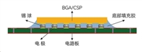 芯片底部填充工艺:提升电子设备可靠性的关键步骤
 REF03GPZ资料解读:主要特征、技术参数、应用场景
工作时间:9:00-21:00
CEO邮箱:ceo@jiepei.com
投诉邮箱:tousu@jiepei.com


 浙公网安备 33010502006866号 浙ICP备10014259号-119
营业执照ICP证
浙公网安备 33010502006866号 浙ICP备10014259号-119
营业执照ICP证


