5秒后页面跳转
ASDM65S180NF PDF预览

ASDM65S180NF

更新时间: 2024-05-23 22:23:30
品牌 Logo 应用领域
安森德 - ASDsemi /
页数 文件大小 规格书
8页 1596K
描述
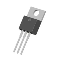
TO-220F

ASDM65S180NF 数据手册

 浏览型号ASDM65S180NF的Datasheet PDF文件第2页浏览型号ASDM65S180NF的Datasheet PDF文件第3页浏览型号ASDM65S180NF的Datasheet PDF文件第4页浏览型号ASDM65S180NF的Datasheet PDF文件第5页浏览型号ASDM65S180NF的Datasheet PDF文件第6页浏览型号ASDM65S180NF的Datasheet PDF文件第7页 
ASDM65S180NF  
650V N-Channel Super-Junction MOSFET  
Features  
Advanced Super Junction Process  
Technology  
Low R  
DS(ON)  
to Minimize Conduction Losses  
Product Summary  
Low Q and Capacitance to Minimize Driver  
g
Losses  
650  
V
m  
A
V
DS  
Superior thermal resistance  
Excellent Gate Charge x R  
DS(ON)  
Product (FOM)  
RDS(on),Typ@VGS =10V  
ID  
160  
Pb-free lead plating; RoHS Compliant  
20  
Application  
Switch Mode Power Supply  
(SMPS)  
(UPS)  
UninterruptiblePower Supply  
Power Factor Correction (PFC)  
G
D
S
TO-220F  
Absolute Maximum Ratings (TJ = 25°C unless otherwise noted)  
Symbol  
VDS  
VGS  
ID  
Parameter  
Value  
Unit  
Drain-Source Voltage  
Gate-Source Voltage  
650  
V
V
±30  
TC =25°C  
TC = 100°C  
TC =25°C  
20  
A
Drain Current-Continuous Note A  
ID  
5.4  
A
A
IDM  
Drain Current-Pulsed Note A, F  
60  
IAS  
Non-repetitive Avalanche Current Note C, E  
Single Pulse Drain-to-Source Avalanche Energy Note C, D  
6
500  
A
EAS  
mJ  
W
Ptot  
Maximum Power Dissipation  
TC =25°C  
33  
TJ, TSTG  
Operating and Storage Temperature Range  
IEC climatic category; DIN IEC 68-1: 55/150/56  
-55 to +150  
°C  
Thermal Resistance Ratings  
Symbol  
Parameter  
Conditions  
Steady State  
Min.  
Typ.  
Max.  
45  
Unit  
RθJA  
RθJS  
Junction-to-Ambient Note B  
-
-
-
-
°C/W  
°C/W  
Junction-to-Soldering Point  
Steady State  
3.8  
Notes:  
A. Repetitive rating, pulse width limited by junction temperature TJmax = +150°C. Ratings are based on low frequency and duty cycles to keep initial TJ = +25°C.  
B. RθJA is the sum of the junction-to-case and case-to-ambient thermal resistance where the case thermal reference is defined as the solder mounting surface of the drain  
pins. RθJS is guaranteed by design while RθCA is determined by the user's board design. RθJA shown below for single device operation on FR-4 in still air.  
C. Limited by TJmax, starting TJ = 25°C, L = 48mH, Rg = 50Ω, VDD = 50V.  
D. IAS and EAS ratings are based on low frequency and duty cycles to keep TJ = +25°C.  
E. Guaranteed by design. Not subject to product testing.  
F. Pulse Test : Pulse Width 100μs, Duty Cycle 2%  
www.ascendsemi.com  
0755-86970486  
NOV 2021 Version1.0  
1/8