
 5秒后页面跳转

| 型号 | 品牌 | 获取价格 | 描述 | 数据表 |
| MMBTA42-13 | DIODES |
获取价格 |
Small Signal Bipolar Transistor, 0.5A I(C), 300V V(BR)CEO, 1-Element, NPN, Silicon, PLASTI |

|
| MMBTA42-28CH-29 | HDSEMI |
获取价格 |
SOT-23 Plastic-Encapsulate Transistors |
|
| MMBTA42-3_15 | KEXIN |
获取价格 |
NPN Transistors |
|
| MMBTA42-7 | DIODES |
获取价格 |
NPN SMALL SIGNAL SURFACE MOUNT TRANSISTOR |
|
| MMBTA42-7-F | DIODES |
获取价格 |
NPN SMALL SIGNAL SURFACE MOUNT TRANSISTOR |
|
| MMBTA42-AE3-R | UTC |
获取价格 |
HIGH VOLTAGE RANSISTOR |
|
| MMBTA42-AH | SWST |
获取价格 |
小信号晶体管 |
|
| MMBTA42-AU | PANJIT |
获取价格 |
SOT-23 |
|
| MMBTA42D87Z | TI |
获取价格 |
200mA, 300V, NPN, Si, SMALL SIGNAL TRANSISTOR, TO-236AB |
|
| MMBTA42E | CJ |
获取价格 |
TRANSISTOR |
|
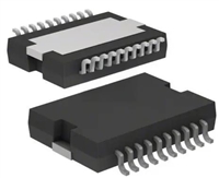 L6234手册解读:引脚信息、电气参数

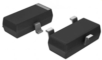 解读BSP135H6327资料:电气参数及替换型号推荐
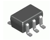 FDG6302P资料解析:电气参数、产品特性
 SBAV99WT1G资料手册:参数信息、产品特性、替代型号推荐
工作时间:9:00-21:00
CEO邮箱:ceo@jiepei.com
投诉邮箱:tousu@jiepei.com


 浙公网安备 33010502006866号 浙ICP备10014259号-119
营业执照ICP证
浙公网安备 33010502006866号 浙ICP备10014259号-119
营业执照ICP证


