
 5秒后页面跳转

| 是否Rohs认证: | 符合 | 生命周期: | Active |
| Reach Compliance Code: | compliant | 风险等级: | 5.8 |
| 其他特性: | HIGH RELIABILITY | 最大集电极电流 (IC): | 0.5 A |
| 集电极-发射极最大电压: | 300 V | 配置: | SINGLE |
| 最小直流电流增益 (hFE): | 40 | JESD-30 代码: | R-PDSO-G3 |
| JESD-609代码: | e3 | 元件数量: | 1 |
| 端子数量: | 3 | 封装主体材料: | PLASTIC/EPOXY |
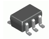
| 封装形状: | RECTANGULAR | 封装形式: | SMALL OUTLINE |
| 峰值回流温度(摄氏度): | 260 | 极性/信道类型: | NPN |
| 参考标准: | AEC-Q101 | 表面贴装: | YES |
| 端子面层: | Matte Tin (Sn) | 端子形式: | GULL WING |
| 端子位置: | DUAL | 处于峰值回流温度下的最长时间: | 30 |
| 晶体管应用: | SWITCHING | 晶体管元件材料: | SILICON |
| 标称过渡频率 (fT): | 50 MHz |
| 型号 | 品牌 | 获取价格 | 描述 | 数据表 |
| MMBTA42-28CH-29 | HDSEMI |
获取价格 |
SOT-23 Plastic-Encapsulate Transistors |

|
| MMBTA42-3_15 | KEXIN |
获取价格 |
NPN Transistors |
|
| MMBTA42-7 | DIODES |
获取价格 |
NPN SMALL SIGNAL SURFACE MOUNT TRANSISTOR |
|
| MMBTA42-7-F | DIODES |
获取价格 |
NPN SMALL SIGNAL SURFACE MOUNT TRANSISTOR |
|
| MMBTA42-AE3-R | UTC |
获取价格 |
HIGH VOLTAGE RANSISTOR |
|
| MMBTA42-AH | SWST |
获取价格 |
小信号晶体管 |
|
| MMBTA42-AU | PANJIT |
获取价格 |
SOT-23 |
|
| MMBTA42D87Z | TI |
获取价格 |
200mA, 300V, NPN, Si, SMALL SIGNAL TRANSISTOR, TO-236AB |
|
| MMBTA42E | CJ |
获取价格 |
TRANSISTOR |
|
| MMBTA42-E6327 | INFINEON |
获取价格 |
Transistor |
|
 L6234手册解读:引脚信息、电气参数

 解读BSP135H6327资料:电气参数及替换型号推荐
 FDG6302P资料解析:电气参数、产品特性
 SBAV99WT1G资料手册:参数信息、产品特性、替代型号推荐
工作时间:9:00-21:00
CEO邮箱:ceo@jiepei.com
投诉邮箱:tousu@jiepei.com


 浙公网安备 33010502006866号 浙ICP备10014259号-119
营业执照ICP证
浙公网安备 33010502006866号 浙ICP备10014259号-119
营业执照ICP证


