
 5秒后页面跳转

| 是否无铅: | 含铅 | 是否Rohs认证: | 不符合 |
| 生命周期: | Obsolete | 零件包装代码: | TO-252 |
| 包装说明: | PLASTIC, CASE 369C-01, DPAK-3 | 针数: | 3 |
| Reach Compliance Code: | not_compliant | HTS代码: | 8541.30.00.80 |
| 风险等级: | 5.16 | 外壳连接: | ANODE |
| 配置: | SINGLE | 关态电压最小值的临界上升速率: | 10 V/us |
| 最大直流栅极触发电流: | 0.075 mA | 最大直流栅极触发电压: | 1 V |
| 最大维持电流: | 10 mA | JESD-30 代码: | R-PSSO-G2 |
| JESD-609代码: | e0 | 最大漏电流: | 0.2 mA |
| 湿度敏感等级: | 1 | 通态非重复峰值电流: | 25 A |
| 元件数量: | 1 | 端子数量: | 2 |
| 最大通态电流: | 2600 A | 最高工作温度: | 110 °C |
| 最低工作温度: | -40 °C | 封装主体材料: | PLASTIC/EPOXY |
| 封装形状: | RECTANGULAR | 封装形式: | SMALL OUTLINE |
| 峰值回流温度(摄氏度): | 240 | 认证状态: | Not Qualified |
| 最大均方根通态电流: | 4 A | 断态重复峰值电压: | 400 V |
| 重复峰值反向电压: | 400 V | 子类别: | Silicon Controlled Rectifiers |
| 表面贴装: | YES | 端子面层: | Tin/Lead (Sn/Pb) |
| 端子形式: | GULL WING | 端子位置: | SINGLE |
| 处于峰值回流温度下的最长时间: | 30 | 触发设备类型: | SCR |
| Base Number Matches: | 1 |
| 型号 | 品牌 | 替代类型 | 描述 | 数据表 |
| MCR706AT4G | ONSEMI |
完全替代  |
Sensitive Gate Silicon Controlled Rectifiers Reverse Blocking Thyristors |

|
| 型号 | 品牌 | 获取价格 | 描述 | 数据表 |
| MCR706AT4-1 | ONSEMI |
获取价格 |
4A, 400V, SCR, CASE 369D-01, DPAK-3 |
|
| MCR706AT4G | ONSEMI |
获取价格 |
Sensitive Gate Silicon Controlled Rectifiers Reverse Blocking Thyristors |
|
| MCR706ATIN/LEAD | CENTRAL |
获取价格 |
Silicon Controlled Rectifier, |
|
| MCR706ATIN/LEAD#N/A | CENTRAL |
获取价格 |
Silicon Controlled Rectifier, |
|
| MCR706ATR13 | CENTRAL |
获取价格 |
Silicon Controlled Rectifier, 4A I(T)RMS, 4000mA I(T), 400V V(DRM), 400V V(RRM), 1 Element |
|
| MCR707A | MOTOROLA |
获取价格 |
Silicon Controlled Rectifiers |
|
| MCR708A | MOTOROLA |
获取价格 |
Silicon Controlled Rectifiers |
|
| MCR708A | ONSEMI |
获取价格 |
Sensitive Gate Silicon Controlled Rectifiers Reverse Blocking Thyristors |
|
| MCR708A | CENTRAL |
获取价格 |
SURFACE MOUNT SILICON CONTROLLED RECTIFIER 4 AMP, 100 THRU 600 VOLTS |
|
| MCR708A | TGS |
获取价格 |
Silicon Controlled Rectifiers |
|
 解读L9904TR手册资料:产品概述、主要功能、电气参数

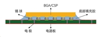 芯片底部填充工艺:提升电子设备可靠性的关键步骤
 REF03GPZ资料解读:主要特征、技术参数、应用场景
 一文带你了解DS28E40主要特征、安全特性、应用场景
工作时间:9:00-21:00
CEO邮箱:ceo@jiepei.com
投诉邮箱:tousu@jiepei.com


 浙公网安备 33010502006866号 浙ICP备10014259号-119
营业执照ICP证
浙公网安备 33010502006866号 浙ICP备10014259号-119
营业执照ICP证


