| 型号 | 品牌 | 获取价格 | 描述 | 数据表 |
| MBR1050CG | SENO |
获取价格 |
10.0A SCHOTTKY BARRIER DIODE |

|
| MBR1050CGD | DYELEC |
获取价格 |
SURFACE MOUNT SCHOTTKYBARRIER RECTIFIERS |

|
| MBR1050CKD | DYELEC |
获取价格 |
SURFACE MOUNT SCHOTTKYBARRIER RECTIFIERS |

|
| MBR1050CT | SIRECTIFIER |
获取价格 |
肖特基势垒二极管Schottky Barrier Diodes,高结温低漏电流肖特基势垒二 |

|
| MBR1050CT | TSC |
获取价格 |
10.0 AMPS. Schottky Barrier Rectifiers |

|
| MBR1050CT | PANJIT |
获取价格 |
10 AMPERES SCHOTTKY BARRIER RECTIFIERS |

|
| MBR1050CT | BL Galaxy Electrical |
获取价格 |
DUAL SCHOTTKY RECTIFIERS |

|
| MBR1050CT | LGE |
获取价格 |
10.0AMP. Schottky Barrier Rectifiers |

|
| MBR1050CT | GXELECTRONICS |
获取价格 |
10.0AMPS. Schottky Barrier Rectifiers |

|
| MBR1050CT | NIUHANG |
获取价格 |
SCHOTTKY RECTIFIERS |

|
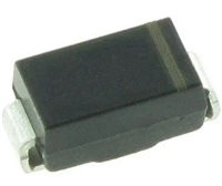
 MBRS340T3G手册解读:参数说明、产品特性及应用

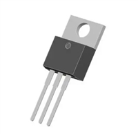
 PMOS管背靠背连接:串联还是并联?

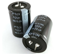
 高压电解电容的分类与选型策略

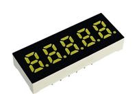
 数码管:基本概念、分类、技术发展及市场趋势
