
 5秒后页面跳转

| 型号 | 品牌 | 获取价格 | 描述 | 数据表 |
| BFG67_15 | JMNIC |
获取价格 |
NPN 8 GHz wideband transistors |

|
| BFG67_2015 | JMNIC |
获取价格 |
NPN 8 GHz wideband transistors |
|
| BFG67-GS08 | VISHAY |
获取价格 |
Transistor |
|
| BFG67R | ETC |
获取价格 |
TRANSISTOR | BJT | NPN | 10V V(BR)CEO | 50MA I(C) | SOT-143R |
|
| BFG67T/R | ETC |
获取价格 |
TRANSISTOR | BJT | NPN | 10V V(BR)CEO | 50MA I(C) | SOT-143 |
|
| BFG67TRL | NXP |
获取价格 |
暂无描述 |
|
| BFG67TRL13 | YAGEO |
获取价格 |
RF Small Signal Bipolar Transistor, 0.05A I(C), 1-Element, Ultra High Frequency Band, Sili |
|
| BFG67W | NXP |
获取价格 |
NPN 8 GHz wideband transistor |
|
| BFG67W/X | NXP |
获取价格 |
NPN 8 GHz wideband transistor |
|
| BFG67W/XR | NXP |
获取价格 |
NPN 8 GHz wideband transistor |
|
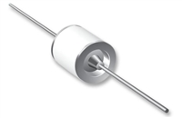 压敏电阻与气体放电管串联使用的专业解析

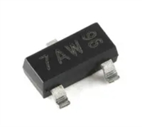 手册解读:MMBT3904参数与管脚图及代换
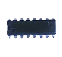 74LS298PC手册解读:参数说明、引脚说明、替代型号推荐
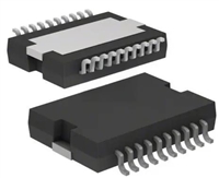 L6234手册解读:引脚信息、电气参数
工作时间:9:00-21:00
CEO邮箱:ceo@jiepei.com
投诉邮箱:tousu@jiepei.com


 浙公网安备 33010502006866号 浙ICP备10014259号-119
营业执照ICP证
浙公网安备 33010502006866号 浙ICP备10014259号-119
营业执照ICP证


