5秒后页面跳转
AD694AQ PDF预览

AD694AQ

更新时间: 2024-02-09 20:11:58
品牌 Logo 应用领域
亚德诺 - ADI 模拟IC信号电路
页数 文件大小 规格书
12页 428K
描述
4.20 mA Transmitter

AD694AQ 技术参数

是否无铅: 含铅是否Rohs认证: 符合
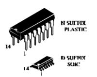
生命周期:Active零件包装代码:DIP
包装说明:DIP,针数:16
Reach Compliance Code:compliantECCN代码:EAR99
HTS代码:8542.39.00.01风险等级:0.64
Samacsys Confidence:3Samacsys Status:Released
Samacsys PartID:169175Samacsys Pin Count:16
Samacsys Part Category:Integrated CircuitSamacsys Package Category:Dual-In-Line Packages
Samacsys Footprint Name:N-16Samacsys Released Date:2015-06-25 00:00:00
Is Samacsys:N模拟集成电路 - 其他类型:ANALOG CIRCUIT
JESD-30 代码:R-PDIP-T16JESD-609代码:e3
长度:20.13 mm功能数量:1
端子数量:16最高工作温度:70 °C
最低工作温度:封装主体材料:PLASTIC/EPOXY
封装代码:DIP封装形状:RECTANGULAR
封装形式:IN-LINE峰值回流温度(摄氏度):NOT APPLICABLE
认证状态:Not Qualified座面最大高度:5.33 mm
最大供电电压 (Vsup):36 V最小供电电压 (Vsup):4.5 V
标称供电电压 (Vsup):24 V表面贴装:NO
温度等级:COMMERCIAL端子面层:Matte Tin (Sn)
端子形式:THROUGH-HOLE端子节距:2.54 mm
端子位置:DUAL处于峰值回流温度下的最长时间:NOT APPLICABLE
宽度:7.62 mmBase Number Matches:1

AD694AQ 数据手册

 浏览型号AD694AQ的Datasheet PDF文件第4页浏览型号AD694AQ的Datasheet PDF文件第5页浏览型号AD694AQ的Datasheet PDF文件第6页浏览型号AD694AQ的Datasheet PDF文件第8页浏览型号AD694AQ的Datasheet PDF文件第9页浏览型号AD694AQ的Datasheet PDF文件第10页 
AD694  
Figure 4. Using Optional Pass Transistor to Minimize Self-Heating Errors; Dual Supply Operation Shown  
POWER DISSIPATION CONSIDERATIONS  
P(TOT) = 2 mA × 24 V + (24 V – 10 V) × 1 mA + (24 V – 0 V) × 20 mA  
The AD694 is rated for operation over its specified temperature  
without the use of an external pass transistor. However, it is  
possible to exceed the absolute maximum power dissipation,  
with some combinations of power supply voltage and voltage  
reference load. The internal dissipation of the part can be calcu-  
lated to determine if there is a chance that the absolute maxi-  
mum dissipation may be exceeded. The die temperature must  
never exceed 150°C.  
= 48 mW + 14 mW + 480 mW = 542 mW  
Using θJC of 30°C/Watt and θCA of 70°C/Watt, (from spec page)  
the junction temperature is:  
TJ = 542 mW (30°C/W + 70°C/W) + 50°C = 104.2°C  
The junction temperature is in the safe region.  
Internal power dissipation can be reduced either by reducing the  
value of θCA through the use of air flow or heat sinks, or by re-  
ducing P(TOT) of the AD694 through the use of an external pass  
transistor. Figure 5 shows the maximum case and still air tem-  
peratures for a given level of power dissipation.  
Total power dissipation (PTOT), is the sum of power dissipated  
by the internal amplifiers, P (Standing), the voltage reference,  
P(VREF) and the current output stage, P(IOUT) as follows:  
PTOT = P (Standing) + P (VREF) + P (IOUT  
)
where:  
P (Standing) = 2 mA (max) × VS  
P (VREF) = (VS – VREF) × IVREF  
P(IOUT) (VS – VOUT) × IOUT (max):  
I
OUT (max) may be the max expected operating cur-  
rent, or the overdriven current of the device.  
P(IOUT) drops to (2 Volts × IOUT) if a pass transistor  
is used.  
Definitions:  
REF = output voltage of reference  
VREF = output current of reference  
VS = supply voltage  
OUT = voltage at IOUT pin.  
V
I
V
An appropriate safety factor should be added to PTOT  
.
Figure 5. Internal Power Dissipation in mW  
The junction temperature may be calculated with the following  
formula:  
ADJUSTMENT PROCEDURES  
The following sections describe methods for trimming the out-  
put current offset, the span and the voltage reference.  
TJ = PTOT (θJC + θCA) + TAMBIENT  
θJC is the thermal resistance between the chip and the package  
(case), θCA is the thermal resistance between the case and its  
surroundings and is determined by the characteristics of the  
thermal connection of the case to ambient.  
ADJUSTING 4 mA ZERO  
The 4 mA zero current may be adjusted over the range of 2 mA  
to 4.8 mA to accommodate large input signal offsets, or to allow  
small adjustment in the zero current. The zero may be adjusted  
by pulling up or down on Pin 6 (4 mA Adj) to increase or de-  
crease the nominal offset current. The 4 mA Adj. (Pin 6) should  
not be driven to a voltage greater than 1 V. The arrangement of  
For example, assume that the part is operating with a VS of 24 V  
in the cerdip package at 50°C, with a 1 mA load on the 10 V  
reference. Assume that IOUT is grounded and that the max IOUT  
would be 20 mA. The internal dissipation would be:  
REV. A  
–7–  

AD694AQ 替代型号

型号 品牌 替代类型 描述 数据表
AD694BQ ADI

完全替代

4.20 mA Transmitter
AD694JNZ ADI

类似代替

4–20 mA Transmitter
AD694JN ADI

类似代替

4.20 mA Transmitter

与AD694AQ相关器件

型号 品牌 获取价格 描述 数据表
AD694AR ADI

获取价格

4.20 mA Transmitter
AD694ARZ ADI

获取价格

4–20 mA Transmitter
AD694ARZ-REEL ADI

获取价格

IC TRANSMITTER 4-20MA 16-SOIC
AD694BQ ADI

获取价格

4.20 mA Transmitter
AD694BR ADI

获取价格

4.20 mA Transmitter
AD694BRZ ADI

获取价格

4–20 mA Transmitter
AD694BRZ-REEL ADI

获取价格

4–20 mA Transmitter
AD694BRZ-REEL7 ADI

获取价格

IC IC,TRANSDUCER SIGNAL CONDITIONER,BIPOLAR,SOP,16PIN,PLASTIC, Analog IC:Other
AD694JCHIPS ADI

获取价格

IC SPECIALTY ANALOG CIRCUIT, UUC, DIE, Analog IC:Other
AD694JN ADI

获取价格

4.20 mA Transmitter