
 5秒后页面跳转

| 生命周期: | Contact Manufacturer | Reach Compliance Code: | unknown |
| ECCN代码: | EAR99 | 风险等级: | 5.76 |
| Base Number Matches: | 1 |
| 型号 | 品牌 | 获取价格 | 描述 | 数据表 |
| GBU6005-G | COMCHIP |
获取价格 |
Glass Passivated Bridge Rectifiers |

|
| GBU6-005-LFR | FRONTIER |
获取价格 |
6A SILICON SINGLE-PHASE BRIDGE RECTIFIERS |
|
| GBU601 | FCI |
获取价格 |
6.0Amps Glass Passivated Single Phase Silico n Bridge |
|
| GBU601 | FORMOSA |
获取价格 |
SURFACE GLASS PASSIVATED BRIDGE RECTIFIER |
|
| GBU601 | ASEMI |
获取价格 |
6.0A Single-Phase Bridge Rectifier |
|
| GBU601 | LGE |
获取价格 |
Single Phase 6.0AMP.Glass Passivated Bridge Rectifiers |
|
| GBU601 | CTC |
获取价格 |
GLASS PASSIVATED BRIDGE RECTIFIERS |
|
| GBU601 | SECOS |
获取价格 |
6 .0 AMP Glass Passivated Bridge Rectifiers |
|
| GBU601 | DIOTECH |
获取价格 |
GLASS PASSIVATED BRIDGE RECTIFIER |
|
| GBU601 | RFE |
获取价格 |
BRIDGE RECTIFIERS 3.0 to 6.0 Amps |
|
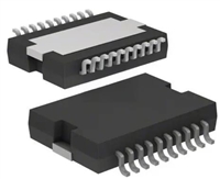 L6234手册解读:引脚信息、电气参数

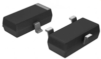 解读BSP135H6327资料:电气参数及替换型号推荐
 FDG6302P资料解析:电气参数、产品特性
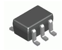
 SBAV99WT1G资料手册:参数信息、产品特性、替代型号推荐
工作时间:9:00-21:00
CEO邮箱:ceo@jiepei.com
投诉邮箱:tousu@jiepei.com


 浙公网安备 33010502006866号 浙ICP备10014259号-119
营业执照ICP证
浙公网安备 33010502006866号 浙ICP备10014259号-119
营业执照ICP证


