5秒后页面跳转
1N4148W PDF预览

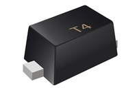
1N4148W

更新时间: 2024-02-27 22:14:11
品牌 Logo 应用领域
德州仪器 - TI 稳压器二极管光电二极管IOT
页数 文件大小 规格书
31页 1178K
描述
LM2736 Thin SOT 750mA Load Step-Down DC-DC Regulator

1N4148W 技术参数

是否Rohs认证: 符合生命周期:Active
Reach Compliance Code:unknownECCN代码:EAR99
HTS代码:8541.10.00.70风险等级:5.76
配置:SINGLE二极管类型:RECTIFIER DIODE
最大正向电压 (VF):0.715 V最大非重复峰值正向电流:2 A
元件数量:1最高工作温度:150 °C
最大输出电流:0.15 A最大重复峰值反向电压:75 V
最大反向恢复时间:0.004 µs子类别:Rectifier Diodes
表面贴装:YESBase Number Matches:1

1N4148W 数据手册

 浏览型号1N4148W的Datasheet PDF文件第5页浏览型号1N4148W的Datasheet PDF文件第6页浏览型号1N4148W的Datasheet PDF文件第7页浏览型号1N4148W的Datasheet PDF文件第9页浏览型号1N4148W的Datasheet PDF文件第10页浏览型号1N4148W的Datasheet PDF文件第11页 
LM2736  
SNVS316F SEPTEMBER 2004REVISED APRIL 2013  
www.ti.com  
V
SW  
D = T /T  
ON SW  
V
IN  
SW  
Voltage  
T
T
OFF  
ON  
0
D
t
V
T
SW  
I
L
I
PK  
Inductor  
Current  
0
t
Figure 20. LM2736 Waveforms of SW Pin Voltage and Inductor Current  
BOOST FUNCTION  
Capacitor CBOOST and diode D2 in Figure 21 are used to generate a voltage VBOOST. VBOOST - VSW is the gate  
drive voltage to the internal NMOS control switch. To properly drive the internal NMOS switch during its on-time,  
VBOOST needs to be at least 1.6V greater than VSW. Although the LM2736 will operate with this minimum voltage,  
it may not have sufficient gate drive to supply large values of output current. Therefore, it is recommended that  
VBOOST be greater than 2.5V above VSW for best efficiency. VBOOST – VSW should not exceed the maximum  
operating limit of 5.5V.  
5.5V > VBOOST – VSW > 2.5V for best performance.  
V
BOOST  
D2  
BOOST  
SW  
V
V
IN  
IN  
C
C
IN  
BOOST  
L
V
OUT  
GND  
C
D1  
OUT  
Figure 21. VOUT Charges CBOOST  
When the LM2736 starts up, internal circuitry from the BOOST pin supplies a maximum of 20mA to CBOOST. This  
current charges CBOOST to a voltage sufficient to turn the switch on. The BOOST pin will continue to source  
current to CBOOST until the voltage at the feedback pin is greater than 1.18V.  
There are various methods to derive VBOOST  
1. From the input voltage (VIN)  
:
2. From the output voltage (VOUT  
)
3. From an external distributed voltage rail (VEXT  
)
4. From a shunt or series zener diode  
In the Simplifed Block Diagram of Figure 19, capacitor CBOOST and diode D2 supply the gate-drive current for the  
NMOS switch. Capacitor CBOOST is charged via diode D2 by VIN. During a normal switching cycle, when the  
internal NMOS control switch is off (TOFF) (refer to Figure 20), VBOOST equals VIN minus the forward voltage of D2  
(VFD2), during which the current in the inductor (L) forward biases the Schottky diode D1 (VFD1). Therefore the  
voltage stored across CBOOST is  
VBOOST - VSW = VIN - VFD2 + VFD1  
(1)  
8
Submit Documentation Feedback  
Copyright © 2004–2013, Texas Instruments Incorporated  
Product Folder Links: LM2736  


与1N4148W相关器件

型号 品牌 描述 获取价格 数据表
1N4148W_05 PANJIT SURFACE MOUNT SWITCHING DIODES

获取价格

1N4148W_06 WTE SURFACE MOUNT FAST SWITCHING DIODE

获取价格

1N4148W_08 BL Galaxy Electrical Silicon Epitaxial Planar Diode

获取价格

1N4148W_09 DIOTEC Surface Mount Small Signal Diodes

获取价格

1N4148W_09 PANJIT SURFACE MOUNT SWITCHING DIODES

获取价格

1N4148W_10 TSC 400mW High Speed SMD Switching Diode

获取价格