
 5秒后页面跳转

| 型号 | 品牌 | 获取价格 | 描述 | 数据表 |
| SN74CBT1G125DBV | TI |
获取价格 |
SINGLE FET BUS SWITCH |

|
| SN74CBT1G125DBVR | TI |
获取价格 |
SINGLE FET BUS SWITCH |
|
| SN74CBT1G125DBVT | TI |
获取价格 |
SN74CBT1G125 SINGLE FET BUS SWITCH |
|
| SN74CBT1G125DCK | TI |
获取价格 |
SINGLE FET BUS SWITCH |
|
| SN74CBT1G125DCKR | TI |
获取价格 |
SN74CBT1G125 SINGLE FET BUS SWITCH |
|
| SN74CBT1G125DCKT | TI |
获取价格 |
SN74CBT1G125 SINGLE FET BUS SWITCH |
|
| SN74CBT1G384 | TI |
获取价格 |
SINGLE FET BUS SWITCH |
|
| SN74CBT1G384DBV | TI |
获取价格 |
SINGLE FET BUS SWITCH |
|
| SN74CBT1G384DBVR | TI |
获取价格 |
SINGLE FET BUS SWITCH |
|
| SN74CBT1G384DBVT | TI |
获取价格 |
SINGLE FET BUS SWITCH |
|
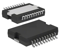 L6234手册解读:引脚信息、电气参数

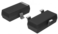 解读BSP135H6327资料:电气参数及替换型号推荐
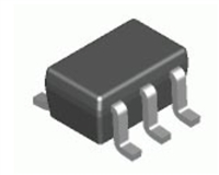 FDG6302P资料解析:电气参数、产品特性
 SBAV99WT1G资料手册:参数信息、产品特性、替代型号推荐
工作时间:9:00-21:00
CEO邮箱:ceo@jiepei.com
投诉邮箱:tousu@jiepei.com


 浙公网安备 33010502006866号 浙ICP备10014259号-119
营业执照ICP证
浙公网安备 33010502006866号 浙ICP备10014259号-119
营业执照ICP证


