
 5秒后页面跳转

| 生命周期: | Obsolete | 包装说明: | , |
| Reach Compliance Code: | unknown | 风险等级: | 5.84 |
| Base Number Matches: | 1 |
| 型号 | 品牌 | 获取价格 | 描述 | 数据表 |
| HN4C51J | TOSHIBA |
获取价格 |
Audio Frequency General Purpose Amplifier Applications |

|
| HN4C51J(TE85L) | TOSHIBA |
获取价格 |
HN4C51J(TE85L) |
|
| HN4D01JU | TOSHIBA |
获取价格 |
Ultra High Speed Switching Applications |
|
| HN4D01JU(TE85L) | TOSHIBA |
获取价格 |
COMMON ANODE DIODE ARRAY,SOT-353 |
|
| HN4D01JU(TE85L,F) | TOSHIBA |
获取价格 |
COMMON ANODE DIODE ARRAY,SOT-353 |
|
| HN4D02JU | TOSHIBA |
获取价格 |
Ultra High Speed Switching Applications |
|
| HN4D02JU(TE85L) | TOSHIBA |
获取价格 |
COMMON CATHODE DIODE ARRAY,SOT-353 |
|
| HN4D02JU(TE85L,F) | TOSHIBA |
获取价格 |
COMMON CATHODE DIODE ARRAY,SOT-353 |
|
| HN4FM | HAMMOND |
获取价格 |
Armoire de plancher a 2 portes en acier doux de type 4 |
|
| HN4FM604810 | HAMMOND |
获取价格 |
Armoire de plancher a 2 portes en acier doux de type 4 |
|
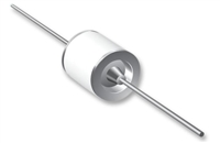 压敏电阻与气体放电管串联使用的专业解析

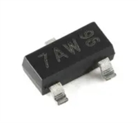 手册解读:MMBT3904参数与管脚图及代换
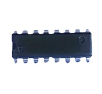 74LS298PC手册解读:参数说明、引脚说明、替代型号推荐
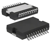 L6234手册解读:引脚信息、电气参数
工作时间:9:00-21:00
CEO邮箱:ceo@jiepei.com
投诉邮箱:tousu@jiepei.com


 浙公网安备 33010502006866号 浙ICP备10014259号-119
营业执照ICP证
浙公网安备 33010502006866号 浙ICP备10014259号-119
营业执照ICP证


