
 5秒后页面跳转

| 型号 | 品牌 | 获取价格 | 描述 | 数据表 |
| CDP1854ACD | INTERSIL |
获取价格 |
Programmable Universal Asynchronous Receiver/Transmitter (UART) |

|
| CDP1854ACD | RENESAS |
获取价格 |
1 CHANNEL(S), 200Kbps, SERIAL COMM CONTROLLER, CDIP40, SIDE BRAZED, DIP-40 |
|
| CDP1854A-CD | ETC |
获取价格 |
Telecommunication IC |
|
| CDP1854ACD/3 | RENESAS |
获取价格 |
IC 1 CHANNEL(S), 215K bps, SERIAL COMM CONTROLLER, CDIP40, Serial IO/Communication Control |
|
| CDP1854ACD3 | INTERSIL |
获取价格 |
High Reliability CMOS Programmable Universal Asynchronous Receiver/Transmitter (UART) |
|
| CDP1854ACD3 | ROCHESTER |
获取价格 |
Serial I/O Controller, 1 Channel(s), 0.030517578125MBps, CMOS, CDIP40, DIP-40 |
|
| CDP1854ACDX | INTERSIL |
获取价格 |
Programmable Universal Asynchronous Receiver/Transmitter (UART) |
|
| CDP1854ACDX | ROCHESTER |
获取价格 |
Serial I/O Controller, 1 Channel(s), 0.0244140625MBps, CMOS, CDIP40, DIP-40 |
|
| CDP1854ACE | INTERSIL |
获取价格 |
Programmable Universal Asynchronous Receiver/Transmitter (UART) |
|
| CDP1854ACE | ROCHESTER |
获取价格 |
Serial I/O Controller, 1 Channel(s), 0.0244140625MBps, CMOS, PDIP40, DIP-40 |
|
 数码管:基本概念、分类、技术发展及市场趋势

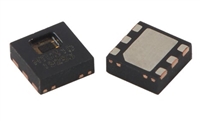 湿度传感器:原理、选型、分类与特性
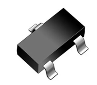 解读SBAT54SLT1G手册:产品概述、参数分析
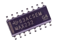 MAX232DR资料:引脚说明、产品特性、电气参数
工作时间:9:00-21:00
CEO邮箱:ceo@jiepei.com
投诉邮箱:tousu@jiepei.com


 浙公网安备 33010502006866号 浙ICP备10014259号-119
营业执照ICP证
浙公网安备 33010502006866号 浙ICP备10014259号-119
营业执照ICP证


