Coaxial
ZFBT-6GW+
ZFBT-6GW
Bias-Tee
50Ω Wideband 0.1 to 6000 MHz
Maximum Ratings
Operating Temperature
Storage Temperature
RF Power
Features
CASE STYLE: K18
• wideband, 0.1 to 6000 MHz
• low insertion loss, 0.6 dB typ.
• good isolation, 40 dB typ.
-55°C to 100°C
-55°C to 100°C
30 dBm max.
30 V max.
Connectors Model
Price
Qty.
(1-9)
(1+)
SMA
ZFBT-6GW(+)
BRACKET (OPTION “B”)
$89.95
$2.50
Voltage at DC port
Applications
• biasing amplifiers
• biasing of laser diodes
• biasing of active antennas
• DC return
+ RoHS compliant in accordance
with EU Directive (2002/95/EC)
The +Suffix has been added in order to identify RoHS
Compliance. See our web site for RoHS Compliance
methodologies and qualifications.
Input Current
500 mA
DC resistance from DC to RF&DC port
4.5 ohm typ.
Coaxial Connections
RF
• DC blocking
• test accessory
1 (SMA female)
2 (SMA male)
3 (SMA female)
RF&DC
DC
Bias-Tee Electrical Specifications
FREQUENCY
(MHz)
INSERTION LOSS*
ISOLATION* (dB)
(RF port to DC port)
(RF&DC port to DC port)
VSWR**
(:1)
(dB)
L
M
U
L
M
U
L
M
U
Outline Drawing
fL
fU
Typ. Max. Typ. Max. Typ. Max. Typ. Min.
0.15 0.8 0.6 1.4 1.0 2.2 25 15
M= mid range (10 fL to fU/2)
* Insertion Loss 1 dB Max. and isolation 7dB Min. 0.1 to 0.3 MHz.
Typ. Min.
40 20
Typ. Min.
30 17
Typ. Max. Typ. Max. Typ. Max.
0.1
6000
1.06 1.6
1.13 1.3
1.13 1.5
L= low range (fL to 10 fL)
U= upper range (fU/2 to fU)
Insertion Loss and Isolation are guaranteed up to 20 dBm-RF power and 200mA DC current.
**VSWR measured with open and short at DC port.
Typical Performance Data
Freq.
(MHz) (dBm)
Pin
INSERTION LOSS (dB)
with Current
ISOLATION (dB)
(Pin= -10dBm) with current
VSWR
(:1)
0mA
20mA 50mA 100mA 150mA 200mA 10mA 20mA 50mA 100mA 150mA 200mA
0.10
0.27
0.53
1.06
10.00
19.80
19.80
19.80
19.80
18.50
0.17
0.13
0.12
0.13
0.16
0.17
0.13
0.12
0.13
0.17
0.16
0.13
0.12
0.12
0.17
0.17
0.14
0.11
0.11
0.16
0.20
0.14
0.11
0.12
0.16
0.24
0.15
0.11
0.12
0.16
19.46
25.86
29.17
30.81
30.06
19.04
25.53
28.98
30.74
30.07
17.83
24.52
28.36
30.56
30.07
14.58
21.43
26.18
29.62
30.20
12.66
19.31
24.40
28.62
30.38
11.75
18.16
23.37
27.92
30.56
1.16
1.07
1.04
1.02
1.04
114.75
324.25
743.25
952.75
1581.25
19.50
19.70
18.70
18.20
18.00
0.22
0.50
0.28
0.31
0.46
0.25
0.55
0.31
0.33
0.48
0.24
0.53
0.30
0.33
0.47
0.22
0.52
0.29
0.31
0.46
0.22
0.53
0.29
0.32
0.48
0.22
0.56
0.29
0.33
0.49
34.45
44.65
51.19
40.75
42.58
34.49
44.61
50.50
40.80
42.59
34.27
44.25
50.16
40.97
43.94
33.99
43.90
50.65
40.97
43.77
33.83
43.91
51.69
40.93
44.36
33.59
43.34
52.47
40.95
44.17
1.07
1.06
1.06
1.11
1.13
Outline Dimensions ( inch
)
mm
2000.25
2524.00
3047.75
3676.25
4200.00
17.10
14.40
14.20
15.10
17.90
0.46
0.40
0.45
0.73
1.04
0.48
0.42
0.48
0.74
1.07
0.47
0.41
0.47
0.75
1.07
0.46
0.42
0.46
0.75
1.06
0.46
0.43
0.46
0.75
1.05
0.47
0.44
0.49
0.75
1.06
45.46
53.15
52.46
46.32
28.42
45.57
53.72
52.25
47.19
28.36
45.73
52.19
51.55
46.36
28.24
45.48
53.17
51.33
45.53
28.14
46.14
52.67
51.46
46.19
28.01
45.28
53.67
50.99
45.65
27.92
1.12
1.12
1.09
1.07
1.09
A
1.25
B
1.25
C
.75
D
.63
E
.38
F
1.00
G
H
.125 1.000
3.18 25.40
31.75 31.75 19.05 16.00
9.65 25.40
J
--
--
K
--
--
L
M
N
2.18
P
.75
Q
wt
.07 grams
1.78 70.0
4502.50
4802.00
5251.75
5550.75
6000.00
-0.60
-0.70
-1.10
-2.00
-2.40
1.17
1.26
1.19
1.65
1.70
1.19
1.26
1.17
1.63
1.71
1.18
1.27
1.16
1.60
1.65
1.19
1.25
1.13
1.56
1.59
1.17
1.22
1.11
1.54
1.54
1.16
1.20
1.09
1.51
1.50
28.15
37.95
49.68
38.44
34.37
28.10
38.01
51.04
38.56
34.36
28.05
38.19
49.12
38.36
34.23
27.96
37.93
49.37
38.07
34.40
27.84
37.58
49.13
37.85
34.49
27.87
37.51
48.19
38.19
34.48
1.14
1.12
1.11
1.10
1.12
.125 1.688
3.18 42.88 55.37 19.05
Electrical Schematic
W
E
N
L
®
L
A
minicircuits.com
Mini-Circuits
REV. A
M98898
ZFBT-6GW
DJ/RS/CP/AM
070607
ISO 9001 ISO 14001 CERTIFIED
P.O. Box 350166, Brooklyn, New York 11235-0003 (718) 934-4500 Fax (718) 332-4661 For detailed performance specs & shopping online see Mini-Circuits web site
The Design Engineers Search Engine Provides ACTUAL Data Instantly From MINI-CIRCUITS At: www.minicircuits.com
RF/IF MICROWAVE COMPONENTS
Page 1 of 2


 意法半导体发布第四代SiC技术,助力电动汽车电驱

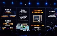
 联发科推出全球首款3纳米汽车芯片CT-X1,挑战高通SA8295

 国家大基金减持三家半导体企业,市场反应各异

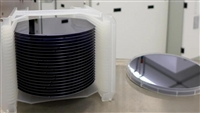
 晶圆厂易主:Coherent公司2000万英镑出售苹果供应链关键资产
