
 5秒后页面跳转

| 品牌 | Logo | 应用领域 |
| PACELEADER | 二极管 | |
| 页数 | 文件大小 | 规格书 |
| 2页 | 134K |  |
| 描述 | ||
| SCHOTTKY BARRIER RECTIFIER | ||

| 型号 | 品牌 | 获取价格 | 描述 | 数据表 |
| SB820_04 | PANJIT |
获取价格 |
SCHOTTKY BARRIER RECTIFIERS |
|
| SB820_06 | WTE |
获取价格 |
8.0A SCHOTTKY BARRIER RECTIFIER |
|
| SB820_09 | PANJIT |
获取价格 |
D2PAK SURFACE MOUNTSCHOTTKY BARRIER RECTIFIER |
|
| SB820_16 | PANJIT |
获取价格 |
D2PAK SURFACE MOUNTSCHOTTKY BARRIER RECTIFIER |
|
| SB820_T0_00001 | PANJIT |
获取价格 |
D2PAK SURFACE MOUNTSCHOTTKY BARRIER RECTIFIER |
|
| SB8200 | CTC |
获取价格 |
SCHOTTKY BARRIER RECTIFIERS |
|
| SB8200 | WON-TOP |
获取价格 |
Powerpack |
|
| SB8200CT | WON-TOP |
获取价格 |
Powerpack |
|
| SB8200D | WON-TOP |
获取价格 |
SMD |
|
| SB8200DC | WON-TOP |
获取价格 |
SMD |
|
 一文带你了解DS28E40主要特征、安全特性、应用场景

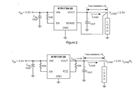 RT9172资料手册解读:关节特性、引脚信息、参数说明
 一文带你了解SM8760CA资料:主要参数特征
 解读MAX3238ECPW:一款多通道RS-232线驱动/接收器
工作时间:9:00-21:00
CEO邮箱:ceo@jiepei.com
投诉邮箱:tousu@jiepei.com


 浙公网安备 33010502006866号 浙ICP备10014259号-119
营业执照ICP证
浙公网安备 33010502006866号 浙ICP备10014259号-119
营业执照ICP证


