Revision 1.02 – June 27, 2006
S5935 – PCI Product
Data Book
LIST OF FIGURES
Figure 1. S5935 Block Diagram ............................................................................................................................... 3
Figure 2. ................................................................................................................................................................ 14
Figure 3. ................................................................................................................................................................ 18
Figure 4. ................................................................................................................................................................ 19
Figure 5. ................................................................................................................................................................ 20
Figure 6. S5933 Pin Assignment ........................................................................................................................... 21
Figure 7. S5935 Signal Pins .................................................................................................................................. 23
Figure 8. Vendor Identification Register ................................................................................................................. 34
Figure 9. Device Identification Register ................................................................................................................. 35
Figure 10. PCI Command Register ........................................................................................................................ 36
Figure 11. PCI Status Register .............................................................................................................................. 38
Figure 12. Revision Identification Register ............................................................................................................ 40
Figure 13. .............................................................................................................................................................. 41
Figure 14. Cache Line Size Register ..................................................................................................................... 45
Figure 15. Latency Timer Register ......................................................................................................................... 46
Figure 16. Header Type Register ........................................................................................................................... 47
Figure 17. Built-In Self Test Register ..................................................................................................................... 48
Figure 18. Base Address Register — Memory ....................................................................................................... 49
Figure 19. Expansion ROM Base Address Register .............................................................................................. 53
Figure 20. Interrupt Line Register .......................................................................................................................... 55
Figure 21. Interrupt Pin Register ............................................................................................................................ 56
Figure 22. Minimum Grant Register ....................................................................................................................... 57
Figure 23. Maximum Latency Register .................................................................................................................. 58
Figure 24. PCI Controlled Bus Master Write Address Register ............................................................................. 62
Figure 25. PCI Controlled Bus Master Write Transfer Count Register ................................................................... 63
Figure 26. PCI Controlled Bus Master Read Address Register ............................................................................. 64
Figure 27. PCI Controlled Bus Master Read Transfer Count Register .................................................................. 65
Figure 28. Mailbox Empty/Full Status Register ...................................................................................................... 66
Figure 29. Interrupt Control/Status Register .......................................................................................................... 68
Figure 30. FIFO Management and Endian Control Byte ........................................................................................ 69
Figure 31. Bus Master Control/Status Register ..................................................................................................... 72
Figure 32. Add-On Controlled Bus Master Write Address Register ....................................................................... 78
Figure 33. Add-On Controlled Bus Master Read Address Register ....................................................................... 80
Figure 34. Add-On Mailbox Empty/Full Status Register ......................................................................................... 81
Figure 35. Add-On Interrupt Control/Status Register ............................................................................................. 83
Figure 36. Add-On General Control/Status Register ............................................................................................. 86
Figure 37. Add-On Controlled Bus Master Write Transfer Count Register ............................................................ 89
Figure 38. Add-On Controlled Bus Master Read Transfer Count Register ............................................................ 90
Figure 39. Serial Interface Definition of Start and Stop .......................................................................................... 94
Figure 40. Serial Interface Clock/Data Relationship .............................................................................................. 94
AMCC Confidential and Proprietary
DS1527
9


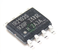
 深入解读IR2103资料手册:引脚说明、电气参数及替换型号推荐

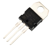
 L7805CV手册解读:引脚说明、替代型号推荐、好坏检测

 MMBT5551资料手册解读:电气参数、替换型号推荐

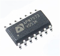
 APW7073资料手册解读:产品特性、引脚说明、替换型号推荐
