CMM3554
P re lim in a ry P ro d u c t In fo rm a t io n
3.45 to 3.5 GHz
7.0V, +24 dBm
W-CDMA Power Amplifier
Au g u s t 1 9 9 9
(1 of 4)
Features
❏ 7.0V Bias Voltage
❏ +24 dBm Linear Output Power (W-CDMA)
❏ 30 dB Gain at Operating Output
Functional Block Diagram
❏ Tested Under Digital Modulation (W-CDMA)
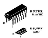
❏ New Low-Cost, Plastic, SO-8 Package
V
1
2
8 RF OUT/+V
d3
g3
7 RF OUT/+V
V
d3
g2
Applications
❏ Wireless Local Loop Subscriber Units
❏ Wireless Local Loop Base Stations
6 V
V
3
d2
g1
5 V
RF IN 4
d1
Back plane is ground and
must be soldered to thermally
conductive ground plane.
The CMM3554 is packaged in a low-cost, space effi-
cient, SO-8 plastic power package that provides excellent elec-
trical stability and low thermal resistance. The part requires
minimal external circuitry for bias and matching to reduce
space and cost.
This device is unconditionally stable under all source
and load impedance.
Description
The CMM3554 is a 7.0 V, +24 dBm, linear power
amplifier intended for use in PCS handsets and wireless local
loop subscriber units and base stations. The amplifier is biased
to meet the requirements of linear modulation systems of
WCDMA.
Absolute Maximum Ratings
Parameter
Rating
Parameter
Rating
Parameter
Rating
Drain Voltage (+V )
d
+8 V*
Power Dissipation
5 W
Operating Temperature
-30°C to +90°C
Drain Current (I )
RF Input Power
DC Gate Voltage (-V )
1.0 A
0 dBm*
-4.0 V*
Thermal Resistance
Storage Temperature
20°C/W
-65°C to +150°C
18 V
Channel Temperature
Soldering Temperature
150°C
240°C for 5 Sec.
d
BV
g
GD
* Max (+V ) and (-V ) under linear operation. Max potential difference across the device at 1dB gain compression point (2V + |-V |) not to exceed the minimum breakdown voltage (BV ) of +18V.
GD
d
g
d
g
Recommended Operating Conditions
Parameter
Typ
Units
Parameter
Typ
Units
Drain Voltage (+V )
d
7.0
Volts
Operating Temperature (PC Board)
-40 to +70
°C
supply voltage is applied to pins 5, 6, 7 and 8. The negative volt-
age supplies control the quiescent current of the device. The quies-
cent current needs to be set at the level specified in order to get the
guaranteed RF performances.
Negative bias voltages can also be used to control the gain,
the output power and the operating current during operation of the
device.
Application Information
The CMM3554 is a three stage amplifier that requires a posi-
tive and a negative supply voltages for proper operation. It is
essential when turning on the device that the negative supply be
applied before the positive supply. When turning the device off,
the positive supply should be removed before the negative supply
is removed.
The CMM3554 can be operated over a range of supply volt-
ages and bias currents. It is important that the maximum power
dissipation specification for the package be observed at all times
and that the maximum voltage across the device not be exceeded.
Matching Circuits Output matching circuit is required to achieve
the output power and gain guaranteed. Celeritek’s recommenda-
tion for the topology of the matching circuit is shown in the
schematic diagram of the test circuit in this data sheet.
In providing both the negative and positive bias voltages, it is
important to provide adequate de-coupling between the RF signal
and the DC voltages. Inadequate de-coupling could result in low
output power, low gain or oscillation. Celeritek recommends the
bias circuits shown in the evaluation circuit .
Circuit Design Considerations
Biasing Three negative voltages are needed to set the bias current
of the 3-stage GaAs FET power amplifier. The first stage bias is
controlled via Vg1. The second stage bias is controlled via Vg2.
The output stage is controlled via Vg3. The recommended divider
networks for each gate bias shown in the schematic. The positive
– Continued on Page 2 –
3236 Scott Boulevard
Santa Clara, California 95054
Phone: (408) 986-5060
Fax: (408) 986-5095


 摩尔斯微电子在美国约书亚树国家公园测试 Wi-Fi HaLow

 贸泽上架Tallysman TW5386智能GNSS天线

 SL74HC10N:高性能三输入与非门解析

 AIC1781A 电池充电控制器深度解析
