5秒后页面跳转
BCW72LT1 PDF预览

BCW72LT1

更新时间: 2024-02-04 09:21:28
品牌 Logo 应用领域
安森美 - ONSEMI 晶体小信号双极晶体管光电二极管
页数 文件大小 规格书
8页 418K
描述
General Purpose Transistor(NPN Silicon)

BCW72LT1 技术参数

是否无铅:不含铅生命周期:Active
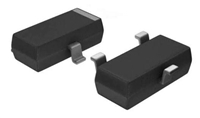
零件包装代码:SOT-23包装说明:SMALL OUTLINE, R-PDSO-G3
针数:3Reach Compliance Code:compliant
ECCN代码:EAR99HTS代码:8541.21.00.75
Factory Lead Time:1 week风险等级:0.58
Samacsys Confidence:3Samacsys Status:Released
Samacsys PartID:224506Samacsys Pin Count:3
Samacsys Part Category:TransistorSamacsys Package Category:SOT23 (3-Pin)
Samacsys Footprint Name:SOT-23 (TO-236) CASE 318-08Samacsys Released Date:2015-07-24 09:18:38
Is Samacsys:N最大集电极电流 (IC):0.1 A
集电极-发射极最大电压:45 V配置:SINGLE
最小直流电流增益 (hFE):200JEDEC-95代码:TO-236AB
JESD-30 代码:R-PDSO-G3JESD-609代码:e3
湿度敏感等级:1元件数量:1
端子数量:3最高工作温度:150 °C
封装主体材料:PLASTIC/EPOXY封装形状:RECTANGULAR
封装形式:SMALL OUTLINE峰值回流温度(摄氏度):260
极性/信道类型:NPN最大功率耗散 (Abs):0.225 W
认证状态:Not Qualified子类别:Other Transistors
表面贴装:YES端子面层:Tin (Sn)
端子形式:GULL WING端子位置:DUAL
处于峰值回流温度下的最长时间:40晶体管应用:SWITCHING
晶体管元件材料:SILICON标称过渡频率 (fT):300 MHz
Base Number Matches:1

BCW72LT1 数据手册

 浏览型号BCW72LT1的Datasheet PDF文件第2页浏览型号BCW72LT1的Datasheet PDF文件第3页浏览型号BCW72LT1的Datasheet PDF文件第4页浏览型号BCW72LT1的Datasheet PDF文件第5页浏览型号BCW72LT1的Datasheet PDF文件第6页浏览型号BCW72LT1的Datasheet PDF文件第8页 
INFORMATION FOR USING THE SOT–23 SURFACE MOUNT PACKAGE  
MINIMUM RECOMMENDED FOOTPRINT FOR SURFACE MOUNTED APPLICATIONS  
Surface mount board layout is a critical portion of the total  
design. The footprint for the semiconductor packages must  
be the correct size to insure proper solder connection  
interface between the board and the package. With the  
correct pad geometry, the packages will self align when  
subjected to a solder reflow process.  
0.037  
0.95  
0.037  
0.95  
0.079  
2.0  
0.035  
0.9  
0.031  
0.8  
inches  
mm  
SOT–23  
SOT–23 POWER DISSIPATION  
The power dissipation of the SOT–23 is a function of the  
SOLDERING PRECAUTIONS  
pad size. This can vary from the minimum pad size for  
soldering to a pad size given for maximum power dissipation.  
Power dissipation for a surface mount device is determined  
The melting temperature of solder is higher than the rated  
temperature of the device. When the entire device is heated  
to a high temperature, failure to complete soldering within a  
short time could result in device failure. Therefore, the  
following items should always be observed in order to  
minimize the thermal stress to which the devices are  
subjected.  
by T  
, the maximum rated junction temperature of the  
, the thermal resistance from the device junction to  
J(max)  
die, R  
θJA  
ambient, and the operating temperature, T . Using the  
A
values provided on the data sheet for the SOT–23 package,  
P
can be calculated as follows:  
D
Always preheat the device.  
The delta temperature between the preheat and  
soldering should be 100°C or less.*  
T
– T  
A
J(max)  
P
=
D
R
θJA  
When preheating and soldering, the temperature of the  
leads and the case must not exceed the maximum  
temperature ratings as shown on the data sheet. When  
using infrared heating with the reflow soldering method,  
the difference shall be a maximum of 10°C.  
The values for the equation are found in the maximum  
ratings table on the data sheet. Substituting these values into  
the equation for an ambient temperature T of 25°C, one can  
A
calculate the power dissipation of the device which in this  
case is 225 milliwatts.  
The soldering temperature and time shall not exceed  
260°C for more than 10 seconds.  
When shifting from preheating to soldering, the  
maximum temperature gradient shall be 5°C or less.  
After soldering has been completed, the device should  
be allowed to cool naturally for at least three minutes.  
Gradual cooling should be used as the use of forced  
cooling will increase the temperature gradient and result  
in latent failure due to mechanical stress.  
150°C – 25°C  
556°C/W  
P
=
= 225 milliwatts  
D
The 556°C/W for the SOT–23 package assumes the use  
of the recommended footprint on a glass epoxy printed circuit  
board to achieve a power dissipation of 225 milliwatts. There  
are other alternatives to achieving higher power dissipation  
from the SOT–23 package. Another alternative would be to  
use a ceramic substrate or an aluminum core board such as  
Thermal Clad . Using a board material such as Thermal  
Clad, an aluminum core board, the power dissipation can be  
doubled using the same footprint.  
Mechanical stress or shock should not be applied during  
cooling.  
* Soldering a device without preheating can cause excessive  
thermal shock and stress which can result in damage to the  
device.  
Motorola Small–Signal Transistors, FETs and Diodes Device Data  
7

BCW72LT1 替代型号

型号 品牌 替代类型 描述 数据表
BCW72LT1G ONSEMI

类似代替

General Purpose Transistor
BCW72,235 NXP

功能相似

BCW71; BCW72 - NPN general purpose transistors TO-236 3-Pin

与BCW72LT1相关器件

型号 品牌 获取价格 描述 数据表
BCW72LT1/D ETC

获取价格

General Purpose Transistor NPN
BCW72LT1D ONSEMI

获取价格

General Purpose Transistor
BCW72LT1G ONSEMI

获取价格

General Purpose Transistor
BCW72LT3 MOTOROLA

获取价格

100mA, 45V, NPN, Si, SMALL SIGNAL TRANSISTOR, TO-236AB
BCW72LX ALLEGRO

获取价格

Small Signal Bipolar Transistor, 45V V(BR)CEO, 1-Element, NPN, Silicon, TO-236AB
BCW72R NXP

获取价格

TRANSISTOR 100 mA, 45 V, NPN, Si, SMALL SIGNAL TRANSISTOR, BIP General Purpose Small Signa
BCW72R VISHAY

获取价格

TRANSISTOR NPN, Si, SMALL SIGNAL TRANSISTOR, TO-236AA, MICRO MINIATURE PACKAGE-3, BIP Gene
BCW72R ALLEGRO

获取价格

Small Signal Bipolar Transistor, 0.1A I(C), NPN
BCW72RL VISHAY

获取价格

TRANSISTOR SMALL SIGNAL TRANSISTOR, TO-236AB, TO-236AB, 3 PIN, BIP General Purpose Small S
BCW72RLK ALLEGRO

获取价格

Small Signal Bipolar Transistor, 45V V(BR)CEO, 1-Element, NPN, Silicon, TO-236AB