
 5秒后页面跳转

| 型号 | 品牌 | 获取价格 | 描述 | 数据表 |
| AS7C251MNTD36A-133BCN | ALSC |
获取价格 |
ZBT SRAM, 1MX36, 10ns, CMOS, PBGA165, LEAD-FREE, BGA-165 |

|
| AS7C251MNTD36A-133BI | ALSC |
获取价格 |
ZBT SRAM, 1MX36, 10ns, CMOS, PBGA165, BGA-165 |
|
| AS7C251MNTD36A-133BIN | ALSC |
获取价格 |
ZBT SRAM, 1MX36, 10ns, CMOS, PBGA165, LEAD-FREE, BGA-165 |
|
| AS7C251MNTD36A-133TQC | ALSC |
获取价格 |
2.5V 1M x 32/36 Pipelined SRAM with NTD |
|
| AS7C251MNTD36A-133TQC | ISSI |
获取价格 |
ZBT SRAM, 1MX36, 3.8ns, CMOS, PQFP100, 14 X 20 MM, TQFP-100 |
|
| AS7C251MNTD36A-133TQCN | ALSC |
获取价格 |
2.5V 1M x 32/36 Pipelined SRAM with NTD |
|
| AS7C251MNTD36A-133TQCN | ISSI |
获取价格 |
ZBT SRAM, 1MX36, 3.8ns, CMOS, PQFP100, 14 X 20 MM, LEAD-FREE, TQFP-100 |
|
| AS7C251MNTD36A-133TQI | ALSC |
获取价格 |
2.5V 1M x 32/36 Pipelined SRAM with NTD |
|
| AS7C251MNTD36A-133TQIN | ISSI |
获取价格 |
ZBT SRAM, 1MX36, 3.8ns, CMOS, PQFP100, 14 X 20 MM, LEAD-FREE, TQFP-100 |
|
| AS7C251MNTD36A-133TQIN | ALSC |
获取价格 |
2.5V 1M x 32/36 Pipelined SRAM with NTD |
|
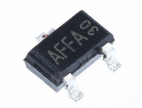 AO3415资料解读:电气参数、替换型号推荐

 电阻上的数字意义及电阻值辨别方法
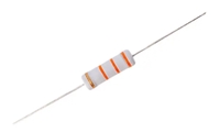 金属氧化膜电阻器:定义、特点与深入解读
 压敏电阻器在直流电路中的过压保护应用探讨
工作时间:9:00-21:00
CEO邮箱:ceo@jiepei.com
投诉邮箱:tousu@jiepei.com


 浙公网安备 33010502006866号 浙ICP备10014259号-119
营业执照ICP证
浙公网安备 33010502006866号 浙ICP备10014259号-119
营业执照ICP证


