ALUMINUM HOUSED RESISTORS
RESISTORSꢀCAPACITORSꢀCOILSꢀDELAY LINES
Term.W is
RoHS
compliant
600 SERIES
ꢀ Widest selection in the industry! 5 to 1000 Watt
ꢀ0.005Ω to1MΩ, tolerance to .01%, TC to 5ppm
Standard units feature lug terminals (605 - 630)
or threaded terminals (635 & 640).
&
260°C
RoHS
compatible
Option L (605-625): Insulated stranded wires
embedded into the case. Black TFE 18awg x
12”L with ¼” strip is standard (16awg TFE &
14awg PVC avail). Also available with 4 insulated
lead wires (Opt.4L), and with a wide variety of
terminals... quick-connect male (Opt. LM=.25x.032);
ꢀ High power and high pulse capacity in compact size
ꢀ Welded wirewound construction, low noise
ꢀ Available on exclusive SWIFT TM delivery program!
ꢀ Option X: Non-inductive
female (Opt. LF=.25x.032”, LFS=.187x.020)
;
ꢀ Option P: Increased pulse capability
ring terminal (Opt. LR=.145” I.D., LRR=.25” I.D.).
ꢀ Option ER: 100 hour burn-in per MIL-PRF-39009
ꢀ Option B: Increased power
Option 2T & 4T (605-625): Straight leadwires.
2T is 2-terminal design, 4T is 4-terminal. Each
have 18awg x 1” min lead length. 16awg x 1”
and 12AWG x .5” also available (12 AWG not
avail in Opt 4T).
ꢀ Additional modifications: unanodized cases, custom marking,
increased dielectric/creepage & working voltage, low thermal emf
(opt.E), etc. Customized components are an RCD Specialty!
A
L
D
605-630
View From Top
605-630
View From Side
B
F
E
G
Option 4R (605-630): 4-terminal design. 16AWG
lug terminals are welded to standard terminals.
N
H
C
Type 630 & 640 have 4 mounting holes
L
A
D
Option Q (605-630): .187x.020” male fast-on
terminal; Opt. Q2 (610-625) is .250x.032”
male terminal. Opt. Q & Q2 add 0.9 ±0.125”
to Dim. D.
635-640
View From Side
635-640
View From Top
B
F
E
G
H
C
1/4-20,12-24
3.00±.01”
(640 only)
SPECIFICATIONS: Consult factory for dimensions on liquid cooled design up to 1000 Watt
Wattage,Mounted
RCD
Type
Resis.
Voltage
A
±.005
B
±.005
C
±.062
D
±.062
E
±.031
F
G
±.031
H
±.010
L
N
Mtg
MIL Type1
Range (Ω) Rating2
±.031
±.005
±.005 Screw
Std
Opt.B MIL
.444
[11.3]
.562
[14.3]
.719
[18.3]
1.563
[39.7]
1.563
[39.7]
.490
[12.5]
.625
[15.9]
.781
[19.8]
.844
[21.5]
.844
[21.5]
.600
[15.2]
.750
[19.0]
1.062
[27.0]
1.968
[50.0]
2.850
[72.4]
2.579 3.38±.09
[65.5]
3.50
[88.9]
4.50
1.125
[28.6]
1.375
[35.0]
1.938
[49.3
2.781
[70.6]
3.663
[93.0]
.334
[8.5]
.420
[10.8]
.531
[13.5]
.609
[15.6]
.646
[16.4]
.800
[20.3]
1.080
[27.4]
1.140
[28.8]
1.140
[28.8]
.320
[8.2]
.405
[10.3]
.546
[13.9]
.610
[15.5]
.610
[15.5]
.065
[1.6]
.075
[1.9]
.088
[2.2]
.088
[2.2]
.088
[2.2]
.093
[2.4]
.093
[2.4]
.125
[3.2]
.125
[3.2]
.125
[3.2]
.050
[1.3]
.086
[2.2]
.086
[2.2]
.086
[2.2]
.086
[2.2]
#2
[M2]
#2
[M2]
#4
[M2.5]
#4
[M2.5]
#4
[M2.5]
#8
[M4]
#8
[M4]
#8
[M4]
605 RE/RER60
7.5
15
20
35
60
-
5
.005-20K
160
265
610 RE/RER65 12.5
10 .005-100K
615 RE/RER70
620 RE/RER75
25
50
20
30
-
.005-200K
.005-400K
.01-500K
0.1-100K
0.1-600K
0.1-1M
550
1250
1900
1900
1900
2300
.609
625
630
635
640
-
75
[15.6]
1.053
[26.7]
1.812
[46.0]
2.125
[53.98]
1.377±.01 1.457±.01
1.839 .960±.05 .138±.03 .173±.01 .086 Min
-
100
100
250
-
-
[35.0]
2.75±.01
[69.85]
3.875±.01
[98.42]
[37.0]
2.25±.01
[57.15]
2.50±.01
[63.5]
[85.9]
[46.7]
2.812
[71.42]
3.00
[24.4]
1.75
[44.45]
2.188
[55.58]
[3.5]
.188±.03 .188±.01
[4.78] [4.78]
.250±.03 .188±.01
[6.35] [4.78]
[4.4]
[2.2]
5.48±.09
[139.14]
7.00±.09
[177.8]
RE77
RE80
150
300
75
120
n/a
n/a
[114.3]
[76.2]
1
2
½
Military part numbers are for reference only and do not imply qualification. Max. voltage = ( PR) , not to exceed the value listed (increased ratings avail). Multiply by 0.7 for Opt.X.
DERATING: Power rating is based on the use of a suitable heat sink and thermal
compound to limit case temp. to 200°C. Derate wattage 0.44%/°C above 25°C.
Recommended aluminum chassis area is 64in² x.040” thick for type 605 and 610,
83in² x.040” thick for type 615, 144in² x.060” thick for type 620, and 144in² x .125”
for types 625 through 640. Without a heat sink, derate wattage rating by 60%.
TYPICALPERFORMANCECHARACTERISTICS:
.005 - .0099Ω: 600ppm std (200, 300ppm opt.)
Temp.Coefficient
.01 - .049Ω:
.05 - .099Ω:
.1 - .99Ω:
300ppm std (100, 200ppm opt.)
200ppm std (50, 100ppm opt.)
90ppm std(10, 20, 30, 50ppm opt)
50ppm std (10, 20, 30ppm opt.)
1 - 9.9Ω:
10Ω & above: 20ppm std (5, 10ppm opt.)
P/NDESIGNATION:
RCD Type
Options: X, Q2, Q, P, LRR, LR, LM, LFS, LF, L, ER,
E, B, 65, 41, 36, 34, 16, 14, 4T, 4R, 4L (leave blank if std)
610 -
1001 - F B
W
Dielectric (DWV)
605, 610
615, 620, 625
630, 635, 640
Inductance, Opt.X
605
610, 615
620, 625
630, 635, 640
Standard3
1KV
2KV
2.5KV
≤50Ω
Optional
2KV (Opt.36), 2.5KV (Opt.34)
2.5KV (Opt.34), 3KV (Opt.41)
3KV (Opt.41), 4KV (Opt.65)
>50Ω
Resis. Code: ≤1%: 3 signif. figures & multiplier,
e.g. R010=0.01Ω, R100= 0.1Ω, 1R00= 1Ω,1000= 100Ω,1001= 1KΩ
Resis. Code 2% - 10%: 2 signif. figures & multiplier, e.g.
R01=0.01Ω, R10= 0.1Ω, 1R0= 1Ω,100= 10Ω,102= 1KΩ
0.2uH Max 0.37uH Max
0.3uH Max 0.6uH Max
0.65uH Max 1.2uH Max
1.5uH Max 3.0uH Max
Tolerance: K=10%, J=5%, H=3%, G=2%, F=1%, D=0.5%,
C=0.25%, B=0.1%, A=0.05%, Q=0.02%, T=0.01%
Packaging: B = standard
Load Life (1000 hrs) ±1% (±2% for 625-640, and ±3% Opt.B)
Moisture Resistance ±0.5%
Overload
Terminal Strength
Operating Temp.
3 The dielectric strength on Opt. L resistors is 50% of standard (available up to 3KV)
5x rated W, 5 Sec (V not to exceed DWV)
10-lb pull test
-55°C to +250°C
Non-std lead length for option L (inches): (12” = std) 4”, 16”, etc.
Optional TC (leave blank if std): 5=5ppm, 10=10ppm; 20=20ppm;
30=30ppm; 50=50ppm; 101=100ppm, 201=200ppm, 301=300ppm)
Termination: W= Lead-free, Q= Tin/Lead (leave blank if either is acceptable)
-
-
-
-
RCD Components Inc, 520 E.Industrial Park Dr, Manchester, NH, USA 03109 rcdcomponents.com Tel: 603 669 0054 Fax: 603 669 5455 Email:sales@rcdcomponents.com
FA018F Sale of this product is in accordance with GF-061. Specifications subject to change without notice.
46


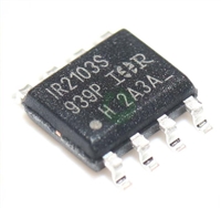
 深入解读IR2103资料手册:引脚说明、电气参数及替换型号推荐

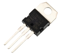
 L7805CV手册解读:引脚说明、替代型号推荐、好坏检测

 MMBT5551资料手册解读:电气参数、替换型号推荐

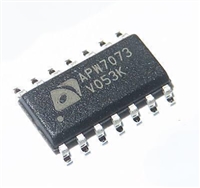
 APW7073资料手册解读:产品特性、引脚说明、替换型号推荐
