
 5秒后页面跳转

| 型号 | 品牌 | 获取价格 | 描述 | 数据表 |
| U2D | YEASHIN |
获取价格 |
SURFACE MOUNT REVERSE VOLTAGE - 50 to 1000 Volts |

|
| U2D | VISHAY |
获取价格 |
Surface Mount Ultrafast Plastic Rectifier |
|
| U2DB | MDD |
获取价格 |
SURFACE MOUNT ULTRAFAST RECOVERY RECTIFIER |
|
| U2D-COP | ETC |
获取价格 |
USB2DEMON BDM/JTAG COP |
|
| U2D-E3/52T | VISHAY |
获取价格 |
Surface Mount Ultrafast Plastic Rectifier |
|
| U2D-E3/5BT | VISHAY |
获取价格 |
Surface Mount Ultrafast Plastic Rectifier |
|
| U2D-E3-52T | VISHAY |
获取价格 |
Surface Mount Ultrafast Plastic Rectifier |
|
| U2D-E3-5BT | VISHAY |
获取价格 |
Surface Mount Ultrafast Plastic Rectifier |
|
| U2DF | YANGJIE |
获取价格 |
SMAF |
|
| U2D-M3 | VISHAY |
获取价格 |
Surface Mount Ultrafast Plastic Rectifier |
|
 数码管:基本概念、分类、技术发展及市场趋势

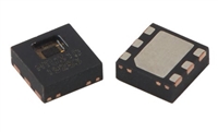 湿度传感器:原理、选型、分类与特性
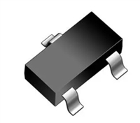 解读SBAT54SLT1G手册:产品概述、参数分析
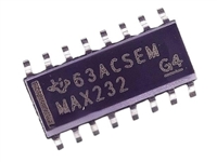 MAX232DR资料:引脚说明、产品特性、电气参数
工作时间:9:00-21:00
CEO邮箱:ceo@jiepei.com
投诉邮箱:tousu@jiepei.com


 浙公网安备 33010502006866号 浙ICP备10014259号-119
营业执照ICP证
浙公网安备 33010502006866号 浙ICP备10014259号-119
营业执照ICP证


