
 5秒后页面跳转

| 是否无铅: | 不含铅 | 生命周期: | Active |
| Reach Compliance Code: | compliant | Factory Lead Time: | 7 weeks |
| 风险等级: | 1.44 | Base Number Matches: | 1 |
| 型号 | 品牌 | 获取价格 | 描述 | 数据表 |
| SZNUD3112LT1G | ONSEMI |
获取价格 |
Integrated Relay, Inductive Load Driver |

|
| SZNUD3124 | ONSEMI |
获取价格 |
Automotive Inductive Load Driver |
|
| SZNUD3124DMT1G | ONSEMI |
获取价格 |
Automotive Inductive Load Driver |
|
| SZNUD3124LT1G | ONSEMI |
获取价格 |
Automotive Inductive Load Driver |
|
| SZNUD3160DMT1G | ONSEMI |
获取价格 |
Industrial Inductive Load Driver |
|
| SZNUD3160LT1G | ONSEMI |
获取价格 |
Industrial Inductive Load Driver |
|
| SZNUD4700SNT1G | ONSEMI |
获取价格 |
LED 分路 |
|
| SZNUF4401MNT1G | ONSEMI |
获取价格 |
EMI 滤波器,4 沟道,带集成式 ESD 保护 |
|
| SZNUF4402MNT1G | ONSEMI |
获取价格 |
EMI 滤波器,4 沟道,带集成式 ESD 保护 |
|
| SZNUF4403MNT1G | ONSEMI |
获取价格 |
EMI 滤波器,4 沟道,带集成式 ESD 保护 |
|
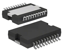 L6234手册解读:引脚信息、电气参数

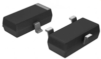 解读BSP135H6327资料:电气参数及替换型号推荐
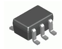 FDG6302P资料解析:电气参数、产品特性
 SBAV99WT1G资料手册:参数信息、产品特性、替代型号推荐
工作时间:9:00-21:00
CEO邮箱:ceo@jiepei.com
投诉邮箱:tousu@jiepei.com


 浙公网安备 33010502006866号 浙ICP备10014259号-119
营业执照ICP证
浙公网安备 33010502006866号 浙ICP备10014259号-119
营业执照ICP证


