
 5秒后页面跳转

| 是否Rohs认证: | 符合 | 生命周期: | Not Recommended |
| 包装说明: | SOP, SOP14,.3 | Reach Compliance Code: | unknown |
| 风险等级: | 5.21 | 信息访问方法: | SERIAL, FIXED PROTOCOL |
| 中断能力: | Y | JESD-30 代码: | R-PDSO-G14 |
| 端子数量: | 14 | 最高工作温度: | 85 °C |
| 最低工作温度: | -40 °C | 封装主体材料: | PLASTIC/EPOXY |
| 封装代码: | SOP | 封装等效代码: | SOP14,.3 |
| 封装形状: | RECTANGULAR | 封装形式: | SMALL OUTLINE |
| 电源: | 3 V | 认证状态: | Not Qualified |
| 子类别: | Timer or RTC | 标称供电电压: | 3 V |
| 表面贴装: | YES | 技术: | CMOS |
| 温度等级: | INDUSTRIAL | 端子形式: | GULL WING |
| 端子节距: | 1.27 mm | 端子位置: | DUAL |
| 最短时间: | SECONDS | 易失性: | YES |
| uPs/uCs/外围集成电路类型: | TIMER, REAL TIME CLOCK | Base Number Matches: | 1 |
| 型号 | 品牌 | 获取价格 | 描述 | 数据表 |
| RX-4801SA:UB | SEIKO |
获取价格 |
Real Time Clock, CMOS, PDSO14, |

|
| RX-4801SA:UB:PURESN | SEIKO |
获取价格 |
Real Time Clock, Volatile, CMOS, PDSO14, |
|
| RX-4801SA:UB0 | SEIKO |
获取价格 |
Real Time Clock, CMOS, PDSO14, |
|
| RX4801SA:UB3:PURESN | SEIKO |
获取价格 |
REAL TIME CLOCK, PDSO14, ROHS COMPLIANT, SOP-14 |
|
| RX-4801SA-0 | SEIKO |
获取价格 |
REAL TIME CLOCK, PDSO14, ROHS COMPLAINT, SOP-14 |
|
| RX-4803 | EPSON |
获取价格 |
REAL TIME CLOCK MODULE (SPI-Bus) |
|
| RX-4803LC | SEIKO |
获取价格 |
Real Time Clock, CMOS, PDSO20, VSOJ-20 |
|
| RX-4803LC:UA | SEIKO |
获取价格 |
REAL TIME CLOCK, PDSO12, ROHS COMPLIANT, VOSJ-12 |
|
| RX-4803LC:UA0:PURESN | SEIKO |
获取价格 |
REAL TIME CLOCK, PDSO12, ROHS COMPLIANT, VSOJ-12 |
|
| RX-4803LC:UA3:PURESN | SEIKO |
获取价格 |
REAL TIME CLOCK, PDSO12, ROHS COMPLIANT, VSOJ-12 |
|
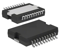 L6234手册解读:引脚信息、电气参数

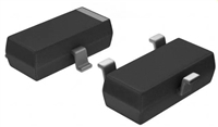 解读BSP135H6327资料:电气参数及替换型号推荐
 FDG6302P资料解析:电气参数、产品特性
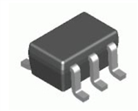
 SBAV99WT1G资料手册:参数信息、产品特性、替代型号推荐
工作时间:9:00-21:00
CEO邮箱:ceo@jiepei.com
投诉邮箱:tousu@jiepei.com


 浙公网安备 33010502006866号 浙ICP备10014259号-119
营业执照ICP证
浙公网安备 33010502006866号 浙ICP备10014259号-119
营业执照ICP证


