
 5秒后页面跳转

| 型号 | 品牌 | 获取价格 | 描述 | 数据表 |
| RF-MOSFET-80V | MICROCHIP |
获取价格 |
The VRF family of RF MOSFETs includes improved replacements forindustry-standard RF transi |

|
| RF-MOSFET-DRIVER | MICROCHIP |
获取价格 |
The DRF1200/01 hybrids integrate drivers, bypass capacitors and RF MOSFETs into a single p |
|
| RFMT-10LM-SM2 | MINI |
获取价格 |
Double Balanced Mixer |
|
| RFMT-10-SM2 | MINI |
获取价格 |
Double Balanced Mixer |
|
| RFMT-12M-SM2 | MINI |
获取价格 |
Double Balanced Mixer |
|
| RFMT-15H-SM2 | MINI |
获取价格 |
Double Balanced Mixer |
|
| RFMT-15M-SM2 | MINI |
获取价格 |
Double Balanced Mixer |
|
| RFMT-15-SM2 | MINI |
获取价格 |
Double Balanced Mixer |
|
| RFMT-17H-SM26 | MINI |
获取价格 |
Double Balanced Mixer |
|
| RFMT-17M-SM26 | MINI |
获取价格 |
Double Balanced Mixer |
|
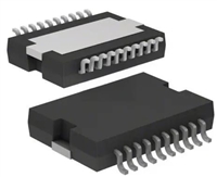 L6234手册解读:引脚信息、电气参数

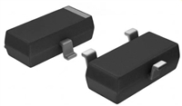 解读BSP135H6327资料:电气参数及替换型号推荐
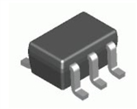 FDG6302P资料解析:电气参数、产品特性
 SBAV99WT1G资料手册:参数信息、产品特性、替代型号推荐
工作时间:9:00-21:00
CEO邮箱:ceo@jiepei.com
投诉邮箱:tousu@jiepei.com


 浙公网安备 33010502006866号 浙ICP备10014259号-119
营业执照ICP证
浙公网安备 33010502006866号 浙ICP备10014259号-119
营业执照ICP证


