
 5秒后页面跳转

| 型号 | 品牌 | 获取价格 | 描述 | 数据表 |
| PSD10-5-1212 | TDK |
获取价格 |
On-board type, Dual Output, Output: 8.4W, +12, +15V |

|
| PSD10-5-1212/S | TDK |
获取价格 |
On-board type, Dual Output, Output: 8.4W, +12, +15V |
|
| PSD108 | POWERSEM |
获取价格 |
Three Phase Rectifier Bridge |
|
| PSD-10M-01 | ETC |
获取价格 |
PUSH SPACER SUPPORT POSTS |
|
| PSD-10M-19 | ETC |
获取价格 |
PUSH SPACER SUPPORT POSTS |
|
| PSD-1100 | CUI |
获取价格 |
DC-DC HOT-SWAP POWER SUPPLY |
|
| PSD-1100_15 | CUI |
获取价格 |
DC-DC HOT-SWAP POWER SUPPLY |
|
| PSD-1100-12-B | CUI |
获取价格 |
DC-DC HOT-SWAP POWER SUPPLY |
|
| PSD-1100-12-F | CUI |
获取价格 |
DC-DC HOT-SWAP POWER SUPPLY |
|
| PSD112 | POWERSEM |
获取价格 |
Three Phase Rectifier Bridges |
|
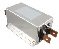 网络滤波器、EMI滤波器与EMC滤波器在电子元器件中的分类关系

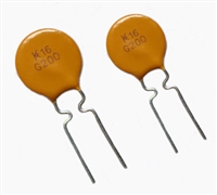 NTC热敏电阻与PTC热敏电阻的应用原理及选型原则
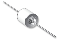 压敏电阻与气体放电管串联使用的专业解析
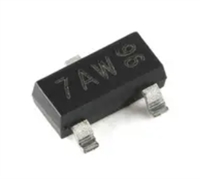 手册解读:MMBT3904参数与管脚图及代换
工作时间:9:00-21:00
CEO邮箱:ceo@jiepei.com
投诉邮箱:tousu@jiepei.com


 浙公网安备 33010502006866号 浙ICP备10014259号-119
营业执照ICP证
浙公网安备 33010502006866号 浙ICP备10014259号-119
营业执照ICP证


