
 5秒后页面跳转

| 是否Rohs认证: | 符合 | 生命周期: | Active |
| 包装说明: | ROHS COMPLIANT, CASE DZ883, 10 PIN | Reach Compliance Code: | not_compliant |
| 风险等级: | 5.69 | 构造: | COMPONENT |
| 最大变频损耗: | 9.1 dB | 最大输入功率 (CW): | 20 dBm |
| 最大工作频率: | 2750 MHz | 最小工作频率: | 2430 MHz |
| 最高工作温度: | 100 °C | 最低工作温度: | -55 °C |
| 射频/微波设备类型: | DOUBLE BALANCED | 最大电压驻波比: | 5.66 |
| Base Number Matches: | 1 |
| 型号 | 品牌 | 获取价格 | 描述 | 数据表 |
| MCA-30 | ASTRODYNE |
获取价格 |
30W Ultraminiature Modular Switching Power Supplies |

|
| MCA3000 | TEKTRONIX |
获取价格 |
Microwave/Counter/Analyzer with Integrated Power |
|
| MCA3027 | TEKTRONIX |
获取价格 |
Microwave/Counter/Analyzer with Integrated Power |
|
| MCA3040 | TEKTRONIX |
获取价格 |
Microwave/Counter/Analyzer with Integrated Power |
|
| MCA-30FH | MINI |
获取价格 |
Double Balanced Mixer, 2960MHz Min, 3060MHz Max, 8.9dB Conversion Loss-Max, CERAMIC, CASE |
|
| MCA-30FLH | MINI |
获取价格 |
Double Balanced Mixer, 2960MHz Min, 3060MHz Max, 8.9dB Conversion Loss-Max, CASE DZ883, 10 |
|
| MCA-30FLH+ | MINI |
获取价格 |
Double Balanced Mixer, 2960MHz Min, 3060MHz Max, 8.9dB Conversion Loss-Max, ROHS COMPLIANT |
|
| MCA-30FMH | MINI |
获取价格 |
Double Balanced Mixer, 2960MHz Min, 3060MHz Max, 8.9dB Conversion Loss-Max, CASE DZ883, 10 |
|
| MCA3200ETL | MOTOROLA |
获取价格 |
MCA3 ETL SERIES MACROCELL ARRAYS |
|
| MCA-352 | MINI |
获取价格 |
Frequency Mixer |
|
 压敏电阻与气体放电管串联使用的专业解析

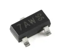 手册解读:MMBT3904参数与管脚图及代换
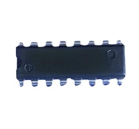 74LS298PC手册解读:参数说明、引脚说明、替代型号推荐
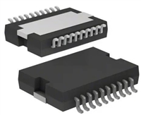 L6234手册解读:引脚信息、电气参数
工作时间:9:00-21:00
CEO邮箱:ceo@jiepei.com
投诉邮箱:tousu@jiepei.com


 浙公网安备 33010502006866号 浙ICP备10014259号-119
营业执照ICP证
浙公网安备 33010502006866号 浙ICP备10014259号-119
营业执照ICP证


