
 5秒后页面跳转

| 型号 | 品牌 | 获取价格 | 描述 | 数据表 |
| MAX2681EUT | MAXIM |
获取价格 |
Down Converter, SOT-23, 6 PIN |

|
| MAX2681EUT+T | MAXIM |
获取价格 |
Down Converter, BIPolar, SOT-23, 6 PIN |
|
| MAX2681EUT-T | MAXIM |
获取价格 |
400MHz to 2.5GHz, Low-Noise, SiGe Downconverter Mixers |
|
| MAX2681EVKIT | MAXIM |
获取价格 |
Easy Evaluation of All Device Functions |
|
| MAX2682 | MAXIM |
获取价格 |
400MHz to 2.5GHz, Low-Noise, SiGe Downconverter Mixers |
|
| MAX2682 | ADI |
获取价格 |
400MHz至2.5GHz、低噪声、SiGe下变频混频器 |
|
| MAX2682EUT | ETC |
获取价格 |
PLASTIC ENCAPSULATED DEVICES |
|
| MAX2682EUT+ | MAXIM |
获取价格 |
Down Converter, BIPolar, SOT-23, 6 PIN |
|
| MAX2682EUT+T | MAXIM |
获取价格 |
暂无描述 |
|
| MAX2682EUT-T | MAXIM |
获取价格 |
400MHz to 2.5GHz, Low-Noise, SiGe Downconverter Mixers |
|
 数码管:基本概念、分类、技术发展及市场趋势

 湿度传感器:原理、选型、分类与特性
 解读SBAT54SLT1G手册:产品概述、参数分析
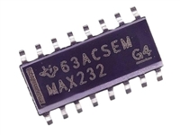 MAX232DR资料:引脚说明、产品特性、电气参数
工作时间:9:00-21:00
CEO邮箱:ceo@jiepei.com
投诉邮箱:tousu@jiepei.com


 浙公网安备 33010502006866号 浙ICP备10014259号-119
营业执照ICP证
浙公网安备 33010502006866号 浙ICP备10014259号-119
营业执照ICP证


