
 5秒后页面跳转

| 是否无铅: | 不含铅 | 是否Rohs认证: | 符合 |
| 生命周期: | Active | 包装说明: | PACKAGE-10/9 |
| Reach Compliance Code: | compliant | ECCN代码: | EAR99 |
| 风险等级: | 5.7 | Is Samacsys: | N |
| 其他特性: | TO BE CLASSIFIED UNDER APSM ACDC; ALSO AVAILABLE INPUT VOLTAGE(AC): 80 TO 120VAC; LG-MAX,WIDTH-MAX | 模拟集成电路 - 其他类型: | DC-DC REGULATED POWER SUPPLY MODULE |
| 最大输入电压: | 170 V | 最小输入电压: | 113 V |
| 标称输入电压: | 141 V | JESD-30 代码: | R-XSMA-T9 |
| JESD-609代码: | e2 | 长度: | 28.2 mm |
| 最大负载调整率: | 0.15% | 功能数量: | 1 |
| 输出次数: | 1 | 端子数量: | 9 |
| 最高工作温度: | 60 °C | 最低工作温度: | -25 °C |
| 最大输出电压: | 13.4 V | 最小输出电压: | 12 V |
| 标称输出电压: | 12.7 V | 封装主体材料: | UNSPECIFIED |
| 封装等效代码: | SIP10,.25 | 封装形状: | RECTANGULAR |
| 封装形式: | MICROELECTRONIC ASSEMBLY | 峰值回流温度(摄氏度): | 260 |
| 认证状态: | Not Qualified | 座面最大高度: | 15.5 mm |
| 子类别: | Power Supply Modules | 表面贴装: | NO |
| 技术: | HYBRID | 温度等级: | OTHER |
| 端子面层: | Tin/Copper (Sn/Cu) | 端子形式: | THROUGH-HOLE |
| 端子节距: | 2.54 mm | 端子位置: | SINGLE |
| 处于峰值回流温度下的最长时间: | NOT SPECIFIED | 最大总功率输出: | 1.27 W |
| 微调/可调输出: | NO | 宽度: | 10.5 mm |
| Base Number Matches: | 1 |
| 型号 | 品牌 | 获取价格 | 描述 | 数据表 |
| BP5033-12_10 | ROHM |
获取价格 |
Non-Isolated AC/DC Converter |

|
| BP5034 | ROHM |
获取价格 |
AC/DC converter unit |
|
| BP5034A12 | ROHM |
获取价格 |
AC / DC converter unit |
|
| BP5034A24 | ROHM |
获取价格 |
AC / DC converter unit |
|
| BP5034A5 | ROHM |
获取价格 |
AC / DC converter unit |
|
| BP5034B20 | ROHM |
获取价格 |
AC100V input, 20V/80mA output |
|
| BP5034B20_10 | ROHM |
获取价格 |
Non-Isolated AC/DC Converter |
|
| BP5034D12 | ROHM |
获取价格 |
AC/DC converter AC100V input, 12V/100mA output |
|
| BP5034D12_10 | ROHM |
获取价格 |
Non-Isolated AC/DC Converter |
|
| BP5034D15 | ROHM |
获取价格 |
AC/DC converter AC100V input, 15V/80mA output |
|
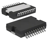 L6234手册解读:引脚信息、电气参数

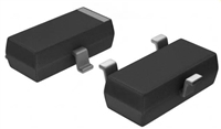 解读BSP135H6327资料:电气参数及替换型号推荐
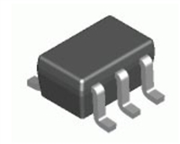 FDG6302P资料解析:电气参数、产品特性
 SBAV99WT1G资料手册:参数信息、产品特性、替代型号推荐
工作时间:9:00-21:00
CEO邮箱:ceo@jiepei.com
投诉邮箱:tousu@jiepei.com


 浙公网安备 33010502006866号 浙ICP备10014259号-119
营业执照ICP证
浙公网安备 33010502006866号 浙ICP备10014259号-119
营业执照ICP证


