
 5秒后页面跳转

| 型号 | 品牌 | 获取价格 | 描述 | 数据表 |
| 8933 | NTE |
获取价格 |
50V CERAMIC DISC |

|
| 89332-0002 | MOLEX |
获取价格 |
PCMCIA Connector, 4 Contact(s), 1 Row(s), Male, Right Angle, 0.039 inch Pitch, Surface Mou |
|
| 8933LEMB120GTN081000 | FH |
获取价格 |
GT系列大容量85℃标准螺栓型电解电容器 |
|
| 893-43-064-30-420000 | MILL-MAX |
获取价格 |
1mm Grid Surface Mount Connectors |
|
| 89347 | NTE |
获取价格 |
50V CERAMIC DISC |
|
| 89358 | IXYS |
获取价格 |
High Voltage IGBT with Diode |
|
| 8936 | ALLEGRO |
获取价格 |
VOICE COIL MOTOR DRIVER |
|
| 89361 | FCI-CONNECTOR |
获取价格 |
2.00mm IDC 0.2,UM Au |
|
| 89361-106LF | AMPHENOL |
获取价格 |
Board Connector, 6 Contact(s), 2 Row(s), Female, 0.079 inch Pitch, IDC Terminal, Locking, |
|
| 89361-108 | AMPHENOL |
获取价格 |
Board Connector, 8 Contact(s), 2 Row(s), Female, 0.079 inch Pitch, IDC Terminal, Locking, |
|
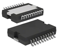 L6234手册解读:引脚信息、电气参数

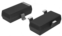 解读BSP135H6327资料:电气参数及替换型号推荐
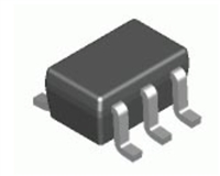 FDG6302P资料解析:电气参数、产品特性
 SBAV99WT1G资料手册:参数信息、产品特性、替代型号推荐
工作时间:9:00-21:00
CEO邮箱:ceo@jiepei.com
投诉邮箱:tousu@jiepei.com


 浙公网安备 33010502006866号 浙ICP备10014259号-119
营业执照ICP证
浙公网安备 33010502006866号 浙ICP备10014259号-119
营业执照ICP证


