
 5秒后页面跳转

| 品牌 | Logo | 应用领域 |
| PACELEADER | 开关 | |
| 页数 | 文件大小 | 规格书 |
| 2页 | 134K |  |
| 描述 | ||
| FAST SWITCHING SURFACE MOUNT RECTIFIER | ||

| 是否Rohs认证: | 符合 | 生命周期: | Active |
| Reach Compliance Code: | compliant | 风险等级: | 5.57 |
| 二极管类型: | RECTIFIER DIODE | 峰值回流温度(摄氏度): | NOT SPECIFIED |
| 处于峰值回流温度下的最长时间: | NOT SPECIFIED | Base Number Matches: | 1 |
| 型号 | 品牌 | 描述 | 获取价格 | 数据表 |
| RS3DCF | BL Galaxy Electrical | 3A,200V,150ns, Surface Mount Fast Recovery Rectifiers |
获取价格 |
|
| RS3D-E3 | VISHAY | DIODE 3 A, 200 V, SILICON, RECTIFIER DIODE, DO-214AB, LEAD FREE, PLASTIC, SMC, 2 PIN, Rect |
获取价格 |
|
| RS3D-E3/57T | VISHAY | DIODE 3 A, 200 V, SILICON, RECTIFIER DIODE, DO-214AB, ROHS COMPLIANT, PLASTIC, SMC, 2 PIN, |
获取价格 |
|
| RS3D-E3/9AT | VISHAY | DIODE 3 A, 200 V, SILICON, RECTIFIER DIODE, DO-214AB, ROHS COMPLIANT, PLASTIC, SMC, 2 PIN, |
获取价格 |
|
| RS3DF | MDD | SURFACE MOUNT FAST RECOVERY RECTIFIER |
获取价格 |
|
| RS3DF | CJ | SMAF |
获取价格 |
|
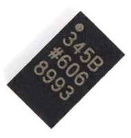 ADXL345传感器工作原理、参数分析、引脚说明

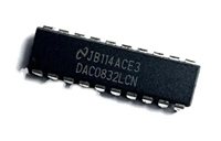 一文带你了解,DAC0832工作原理、输出电压范围、分辨率等参数
 ACS712电流检测使用指南及资料手册参数分析
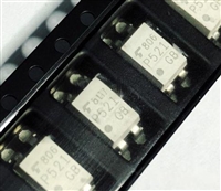 TLP521资料手册解读:参数分析、引脚说明、典型电路
工作时间:9:00-21:00
CEO邮箱:ceo@jiepei.com
投诉邮箱:tousu@jiepei.com


 浙公网安备 33010502006866号 浙ICP备10014259号-119
营业执照ICP证
浙公网安备 33010502006866号 浙ICP备10014259号-119
营业执照ICP证


