MS82C55A, MQ82C55A, MP82C55A
Operational Description
CONTROL WORD
D7 D6 D5 D4 D3 D2 D1 D0
Mode Selection
GROUP B
There are three basic modes of operation than can be
selected by the system software:
Mode 0 - Basic Input/Output
PORT C (LOWER)
1 = INPUT
0 = OUTPUT
Mode 1 - Strobed Input/Output
Mode 2 - Bidirectional Bus
PORT B
1 = INPUT
0 = OUTPUT
MODE SELECTION
0 = MODE 0
When the reset input goes “high”, all ports will be set to the
input mode. After the reset is removed, the 82C55A can
remain in the input mode with no additional initialization
required. The control word register will contain 9Bh. During
the execution of the system program, any of the other modes
may be selected using a single output instruction. This
allows a single 82C55A to service a variety of peripheral
devices with a simple software maintenance routine. Any
port programmed as an output port is initialized to all zeros
when the control word is written.
1 = MODE 1
GROUP A
PORT C (UPPER)
1 = INPUT
0 = OUTPUT
PORT A
1 = INPUT
0 = OUTPUT
MODE SELECTION
00 = MODE 0
01 = MODE 1
1X = MODE 2
ADDRESS BUS
CONTROL BUS
DATA BUS
MODE SET FLAG
1 = ACTIVE
FIGURE 4. MODE DEFINITION FORMAT
RD, WR
B
D7-D0
A0-A1
CS
The modes for Port A and Port B can be separately defined,
while Port C is divided into two portions as required by the
Port A and Port B definitions. All of the output registers,
including the status flip-flops, will be reset whenever the
mode is changed. Modes may be combined so that their
functional definition can be “tailored” to almost any I/O
structure. For instance: Group B can be programmed in
Mode 0 to monitor simple switch closings or display
computational results, Group A could be programmed in
Mode 1 to monitor a keyboard or tape reader on an interrupt-
driven basis.
82C55A
C
MODE 0
MODE 1
A
8
8
I/O
4
I/O
4
I/O
I/O
PB7-PB0
PC3-PC0 PC7-PC4
C
PA7-PA0
A
B
8
I/O
8
I/O
PB7-PB0
CONTROL CONTROL PA7-PA0
OR I/O OR I/O
The mode definitions and possible mode combinations may
seem confusing at first, but after a cursory review of the
complete device operation a simple, logical I/O approach will
surface. The design of the 82C55A has taken into account
things such as efficient PC board layout, control signal definition
vs. PC layout and complete functional flexibility to support
almost any peripheral device with no external logic. Such
design represents the maximum use of the available pins.
MODE 2
C
B
A
BI-
8
I/O
DIRECTIONAL
PB7-PB0
PA7-PA0
CONTROL
FIGURE 3. BASIC MODE DEFINITIONS AND BUS INTERFACE
Single Bit Set/Reset Feature (Figure 5)
Any of the eight bits of Port C can be Set or Reset using a
single Output instruction. This feature reduces software
requirements in control-based applications.
When Port C is being used as status/control for Port A or B,
these bits can be set or reset by using the Bit Set/Reset
operation just as if they were output ports.
FN6140.2
June 15, 2006
5

 5秒后页面跳转


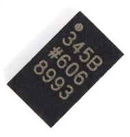 ADXL345传感器工作原理、参数分析、引脚说明

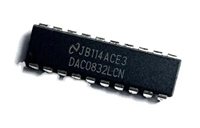 一文带你了解,DAC0832工作原理、输出电压范围、分辨率等参数
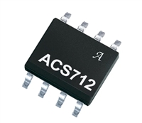 ACS712电流检测使用指南及资料手册参数分析
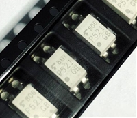 TLP521资料手册解读:参数分析、引脚说明、典型电路


 浙公网安备 33010502006866号 浙ICP备10014259号-119
营业执照ICP证
浙公网安备 33010502006866号 浙ICP备10014259号-119
营业执照ICP证


