
 5秒后页面跳转

| 型号 | 品牌 | 获取价格 | 描述 | 数据表 |
| MBR1030CT-BP | MCC |
获取价格 |
Rectifier Diode, Schottky, 1 Phase, 2 Element, 5A, 30V V(RRM), Silicon, TO-220AB, ROHS COM |

|
| MBR1030CT-BP-HF | MCC |
获取价格 |
Rectifier Diode, Schottky, 1 Phase, 2 Element, 5A, 30V V(RRM), Silicon, TO-220AB, |
|
| MBR1030DCT | NIUHANG |
获取价格 |
SCHOTTKY RECTIFIERS |
|
| MBR1030DD | NIUHANG |
获取价格 |
SCHOTTKY RECTIFIERS |
|
| MBR1030DFCT | NIUHANG |
获取价格 |
SCHOTTKY RECTIFIERS |
|
| MBR1030DS | NIUHANG |
获取价格 |
SCHOTTKY RECTIFIERS |
|
| MBR1030F | MCC |
获取价格 |
10 Amp Schottky Barrier Rectifier 20 to 100 Volts |
|
| MBR1030F | KERSEMI |
获取价格 |
Low Power Loss |
|
| MBR1030F-B | MCC |
获取价格 |
暂无描述 |
|
| MBR1030F-BP | MCC |
获取价格 |
Rectifier Diode, Schottky, 1 Phase, 1 Element, 10A, 30V V(RRM), Silicon, TO-220AC, ROHS CO |
|
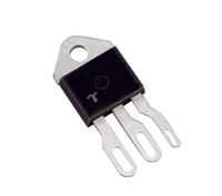 晶闸管的静态特性与伏安特性详解

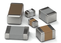 贴片电容的工作原理与参数识别
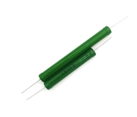 精密电路设计中的高精电阻:分流电阻
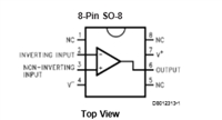 LM7131ACM5手册详解:微型高速单电源运算放大器的深度剖析
工作时间:9:00-21:00
CEO邮箱:ceo@jiepei.com
投诉邮箱:tousu@jiepei.com


 浙公网安备 33010502006866号 浙ICP备10014259号-119
营业执照ICP证
浙公网安备 33010502006866号 浙ICP备10014259号-119
营业执照ICP证


