ISL78227
Functional Pin Description(Continued)
PIN NAME
PIN #
DESCRIPTION
IMON
6
The average current monitor pin for the sum of the two phases’ inductor currents. It is used for average current limiting and average
current protection functions.
The sourcing current from the IMON pin is the sum of the two CSA outputs plus a fixed 17µA offset current. With each CSA sensing
individual phase’s inductor current, the IMON signal represents the sum of the two phases’ inductor currents and is the input current
for the boost. Place a resistor in parallel with a capacitor from IMON to ground. The IMON pin output current signal builds up the
average voltage signal representing the average current sense signals.
A constant average current-limiting function and an average current protection are implemented based on the IMON signal.
• Constant Current Control: A Constant Current (CC) control loop controls the IMON average current signal equal to a 1.6V
reference (VREF_CC), which ultimately limits the total input average current to a constant level.
• Average Current Protection: If the IMON pin voltage is higher than 2V, the part goes into either Hiccup or Latch-off fault
protection depending on the HIC/LATCH pin configuration.
Refer to “Average Current Sense for Two Phases - IMON” on page 31 for more details.
TRACK
PGOOD
7
8
External reference input pin for the IC output voltage regulation loop to follow. The input reference signal can be either a digital or
analog signal selected by the ATRK/DTRK pin configuration. If the TRACK function is not used, connect the TRACK pin to VCC and
the internal VREF_1.6V works as the reference. Refer to “Digital/Analog Track Function” on page 25 for more details.
Provides an open-drain, power-good signal. Pull up this pin with a resistor to this IC’s VCC for proper function. When the output
voltage is within OV/UV thresholds and soft-start is completed, the internal PGOOD open-drain transistor is open and PGOOD is
pulled HIGH. It is pulled low when output UV/OV or input OV conditions are detected. Refer to “PGOOD Signal” on page 30 for more
details.
FSYNC
9
Dual-function pin for switching frequency setting and synchronization is defined as follows:.
• The PWM switching frequency can be programmed by a resistor R
from this pin to ground. PWM frequency refers to
FSYNC
a single-phase switching frequency in this datasheet. The typical programmable frequency range is 50kHz to 1.1MHz.
• The PWM switching frequency can also be synchronized to an external clock applied on the FSYNC pin. The FSYNC pin
detects the input clock signal’s rising edge that it is to be synchronized with. The typical detectable minimum pulse width
of the input clock is 20ns. The rising edge of LG1 is delayed by 35ns from the rising edge of the input clock signal at the
FSYNC pin. When the internal clock is locked to the external clock, it latches to the external clock. If the external clock on
the FSYNC pin is removed, the switching frequency oscillator shuts down. The part then detects PLL_LOCK fault and goes
to either Hiccup mode or Latch-off mode, depending on the HIC/LATCHOFF pin configuration. If the part is set in Hiccup
mode, it restarts with frequency set by R
.
FSYNC
The typical synchronization frequency range is 50kHz to 1.1MHz. The phase dropping mode is not allowed with external
synchronization. Refer to “Oscillator and Synchronization” on page 27 for more details.
HIC/LATCH
10
Select either Hiccup or Latch-off response to faults including output overvoltage (monitoring the FB pin), output undervoltage
(monitoring the FB pin, default inactive), V overvoltage (monitoring the FB pin), peak overcurrent protection (OC2_PEAK),
IN
and average current protection (monitoring the IMON pin), etc.
Set HIC/LATCH = HIGH to activate the Hiccup fault response.
Set HIC/LATCH = LOW to activate the Latch-off fault response. Either toggling the EN pin or recycling VCC POR resets the IC
from Latch-off status. Refer to “Selectable Hiccup or Latch-Off Fault Response” on page 33 for more details.
DE/PHDRP
RBLANK
11
12
Selects Diode Emulation mode (DE), Phase Dropping (PH_DROP) mode, or Continuous Conduction Mode (CCM). The three
configurable modes are: DE mode, DE plus PH_DROP mode, and CCM mode.
Refer to Table 2 on page 33 for the three configurable options. PD_DROP mode is not allowed with external synchronization.
A resistor from this pin to ground programs the blanking time for current sensing after the PWM is ON (LG is ON). This blanking
time is also called t
time, meaning the minimum ON-time when a PWM pulse is ON. Refer to “Minimum On-Time (Blank
MINON
Time) Consideration” on page 28 for the selection of R
.
BLANK
PLLCOMP
EN
13
14
Compensation node for the switching frequency clock’s PLL (Phase Lock Loop). A second order passive loop filter connected
between this pin and ground compensates the PLL. Refer to “Oscillator and Synchronization” on page 27 for more details.
Threshold-sensitive enable input for the controller. When the EN pin is driven above 1.21V (typical), the ISL78227 is enabled
and the internal LDO is activated to power up PVCC followed by a start-up procedure. Driving the EN pin below 0.95V disables
the IC and clears all fault states. Refer to “Enable” on page 30 for more details.
CLKOUT
15
Outputs a clock signal with same frequency to one phase’s switching frequency. The rising edge signal on the CLKOUT pinis delayed
by 90° from the rising edge of LG1 of the same IC. With CLKOUT connected to the FSYNC pin of the second ISL78227, a 4-phase
interleaving operation can be achieved. Refer to “Oscillator and Synchronization” on page 27 for more details.
FN8808 Rev.6.00
Oct 22, 2021
Page 4 of 43

 5秒后页面跳转


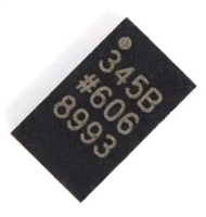 ADXL345传感器工作原理、参数分析、引脚说明

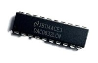 一文带你了解,DAC0832工作原理、输出电压范围、分辨率等参数
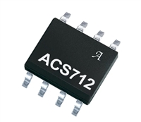 ACS712电流检测使用指南及资料手册参数分析
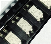 TLP521资料手册解读:参数分析、引脚说明、典型电路


 浙公网安备 33010502006866号 浙ICP备10014259号-119
营业执照ICP证
浙公网安备 33010502006866号 浙ICP备10014259号-119
营业执照ICP证


