ISL5961
Absolute Maximum Ratings
Thermal Information
o
Digital Supply Voltage DV
to DCOM . . . . . . . . . . . . . . . . . +3.6V
to ACOM. . . . . . . . . . . . . . . . . . +3.6V
Thermal Resistance (Typical, Note 1)
( C/W)
DD
Analog Supply Voltage AV
JA
DD
SOIC Package . . . . . . . . . . . . . . . . . . . . . . . . . . . . .
TSSOP Package . . . . . . . . . . . . . . . . . . . . . . . . . . .
75
110
Grounds, ACOM TO DCOM . . . . . . . . . . . . . . . . . . . -0.3V to +0.3V
Digital Input Voltages (D9-D0, CLK, SLEEP). . . . . . . . DV
Reference Input Voltage Range. . . . . . . . . . . . . . . . . . AV
o
+ 0.3V
+ 0.3V
DD
DD
Maximum Junction Temperature . . . . . . . . . . . . . . . . . . . . . . .150 C
Maximum Storage Temperature Range. . . . . . . . . . -65 C to 150 C
Maximum Lead Temperature (Soldering 10s) . . . . . . . . . . . . .300 C
o
o
o
Analog Output Current (I
) . . . . . . . . . . . . . . . . . . . . . . . . . 24mA
OUT
(SOIC - Lead Tips Only)
Operating Conditions
o
o
Temperature Range . . . . . . . . . . . . . . . . . . . . . . . . . . -40 C to 85 C
CAUTION: Stresses above those listed in “Absolute Maximum Ratings” may cause permanent damage to the device. This is a stress only rating and operation of the
device at these or any other conditions above those indicated in the operational sections of this specification is not implied.
NOTE:
1. is measured with the component mounted on an evaluation PC board in free air.
JA
o
Electrical Specifications AV = DV = +3.3V, V
= Internal 1.2V, IOUTFS = 20mA, T = 25 C for All Typical Values
A
DD
DD
REF
o
o
T
= -40 C TO 85 C
A
PARAMETER
SYSTEM PERFORMANCE
Resolution
TEST CONDITIONS
MIN
TYP
MAX
UNITS
14
-5
-
-
Bits
LSB
LSB
Integral Linearity Error, INL
Differential Linearity Error, DNL
“Best Fit” Straight Line (Note 7)
(Note 7)
2.5
1.5
+5
+3
-3
Offset Error, I
IOUTA (Note 7)
(Note 7)
-0.006
-
+0.006 % FSR
OS
Offset Drift Coefficient
0.1
-
ppm
o
FSR/ C
Full Scale Gain Error, FSE
With External Reference (Notes 2, 7)
With Internal Reference (Notes 2, 7)
With External Reference (Note 7)
-3
-3
-
0.5
0.5
50
+3
+3
-
% FSR
% FSR
ppm
Full Scale Gain Drift
o
FSR/ C
With Internal Reference (Note 7)
(Note 3)
-
100
-
ppm
FSR/ C
o
Full Scale Output Current, I
2
-
-
20
mA
V
FS
Output Voltage Compliance Range
-1.0
1.25
DYNAMIC CHARACTERISTICS
Maximum Clock Rate, f
Maximum Clock Rate, f
Output Rise Time
Output Fall Time
ISL5961/2IA, ISL5961/2IB
ISL5961IA, ISL5961IB
Full Scale Step
210
250
150
1.5
1.5
10
-
-
-
-
-
-
-
MHz
MHz
ns
CLK
130
CLK
-
-
-
-
-
Full Scale Step
ns
Output Capacitance
Output Noise
pF
IOUTFS = 20mA
IOUTFS = 2mA
50
pA/Hz
pA/Hz
30
AC CHARACTERISTICS (Using Figure 13 with R
= 50 and R
= 50, Full Scale Output = -2.5dBm
DIFF
LOAD
Spurious Free Dynamic Range,
SFDR Within a Window
f
= 210MSPS, f
= 210MSPS, f
= 130MSPS, f
= 80.8MHz, 30MHz Span (Notes 4, 7)
-
-
-
73
82
86
-
-
-
dBc
dBc
dBc
CLK
OUT
OUT
OUT
f
= 40.4MHz, 30MHz Span (Notes 4, 7)
= 20.2MHz, 20MHz Span (Notes 4, 7)
CLK
f
CLK
FN6007 Rev 4.00
Oct 7, 2015
Page 4 of 14

 5秒后页面跳转


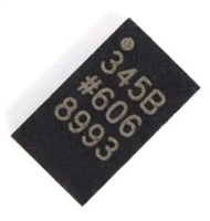 ADXL345传感器工作原理、参数分析、引脚说明

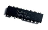 一文带你了解,DAC0832工作原理、输出电压范围、分辨率等参数
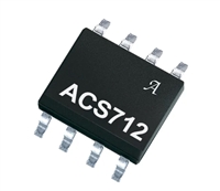 ACS712电流检测使用指南及资料手册参数分析
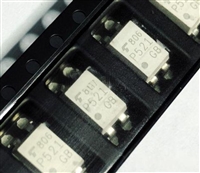 TLP521资料手册解读:参数分析、引脚说明、典型电路


 浙公网安备 33010502006866号 浙ICP备10014259号-119
营业执照ICP证
浙公网安备 33010502006866号 浙ICP备10014259号-119
营业执照ICP证


