Multilayer Ceramic Capacitors
Multilayer Ceramic Capacitors
Series:
ECJ, ECY, ECD
Handling Precautions
Safety Precautions
Multilayer Ceramic Chip Capacitors (hereafter referred to as “Capacitors”) should be used for general purpose
applications found in consumer electronics (audio/visual, home, office, information & communication) equipment.
When subjected to severe electrical, environmental, and/or mechanical stress beyond the specifications, as noted
in the Ratings and Specified Conditions section, the capacitor may fail in a short circuit mode or in an open-circuit
mode. This case results in a burn-out, smoke or flaming.
For products which require high safety levels, please carefully consider how a single malfunction can affect your
product. In order to ensure the safety in the case of a single malfunction, please design products with fail-safe,
such as setting up protecting circuits, etc.
For the following applications and conditions, please contact us for additional specifications not found in this document.
·When your application may have difficulty complying with the safety or handling precautions specified below.
·For any applications where a malfunction with this product may directly or indirectly cause hazardous
conditions which could result in death or injury;
●
Aircraft and Aerospace Equipment (artificial satellite, rocket, etc.)
Submarine Equipment (submarine repeating equipment, etc.)
Transportation Equipment (motor vehicles, airplanes, trains, ship, traffic signal controllers, etc.)
Power Generation Control Equipment (atomic power, hydroelectric power, thermal power plant control system, etc.)
Medical Equipment (life-support equipment, pacemakers, dialysis controllers, etc.)
Information Processing Equipment (large scale computer systems, etc.)
Electric Heating Appliances, Combustion devices (gas fan heaters, oil fan heaters, etc.)
Rotary Motion Equipment
1
2
3
4
5
6
7
8
9
J
Security Systems
And any similar types of equipment
Operating Conditions and Circuit Design
■
1. Circuit Design
1.4 Temperature Rise due to Dielectric Loss of
the Capacitors
1.1 Operating Temperature and Storage Temperature
The specified “Operating Temperature Range” found
in the specifications is the absolute maximum and
minimum temperature rating. Every Capacitor shall be
operated within the specified “Operating Temperature
Range”.
The capacitors mounted on PCB shall be stored
without operating within the specified “Storage
Temperature Range” in the Specifications.
The “Operating Temperature Range” mentioned above
shall include a maximum surface temperature rise of
20 °C, which is caused by the Dielectric loss of the
Capacitor and applied electrical stresses such as
voltage, frequency and wave form. It is recommended
to measure and check the “Surface Temperature of the
Capacitor” in the application at room temperature (up
to 25 °C).
1.2 Design of Voltage Application
Capacitors shall not be operated in excess of the
specified “Rated Voltage” in the Specification.
If voltage ratings are exceeded, the Capacitors could
result in failure or damage. The designed peak DC and
AC voltages applied to the Capacitors, shall be within
the specified “Rated Voltage”.
1.5 Environmental Restrictions
The Capacitors shall not be operated and/or stored
under the following conditions.
(1) Environmental conditions
(a) Under direct exposure to water or salt water
(b) Under conditions where water can condense
and/or dew can form
(c) Under conditions containing corrosive gases
such as hydrogen sulfide, sulfurous acid, chlorine
and ammonia
In case of AC of pulse voltage, the peak voltage shall
be within the specified “Rated Voltage”. If high frequency
voltage or fast rising pulse voltages are continuously
applied, even when within the “Rated Voltage”, consider
that the reliability of the Capacitor may change. Continuous
application of those types of voltages can affects the life of
the Capacitors.
(2) Mechanical conditions
Under severe conditions of vibration or impact beyond
the specified conditions found in the Specifications
1.3 Charging and Discharging Current
1.6 DC Voltage Characteristics
The Capacitors shall not be operated beyond the specified
“Maximum Charging/Discharging Current Ratings” in
the specifications. For safety reasons Panasonic does
not recommend use in applications with low impedance
circuitry such as “secondary power circuits”.
The Capacitors (Class 2) employ dielectric ceramics with
dielectric constant having voltage dependency, and if
the applied DC voltage is high, capacitance may broadly
change. For the specified capacitance, the following
should be confirmed.
Design and specifications are each subject to change without notice. Ask factory for the current technical specifications before purchase and/or use.
Should a safety concern arise regarding this product, please be sure to contact us immediately.
00 Sep. 2008
– EC48 –


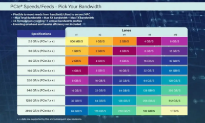 PCIe 8.0规范草案获里程碑进展:256GT/s速率开启1TB/s带宽时代

 寒武纪紧急辟谣背后:AI芯片龙头的真实现状与投资陷阱
 英伟达50亿入股英特尔:芯片巨头联手剑指AMD,行业格局生变
 闪迪预警:NAND闪存供应短缺将持续至2026年


 浙公网安备 33010502006866号 浙ICP备10014259号-119
营业执照ICP证
浙公网安备 33010502006866号 浙ICP备10014259号-119
营业执照ICP证


