
| 型号 | 品牌 | 获取价格 | 描述 | 数据表 |
| CAT521J | CATALYST |
获取价格 |
Analog Circuit, 1 Func, PDSO14, SOIC-14 |

|
| CAT521J-TE10 | CATALYST |
获取价格 |
Configured Digitally Programmable Potentiometer |
|
| CAT521J-TE13 | ETC |
获取价格 |
DIGITAL POTENTIOMETER|SOP|14PIN|PLASTIC |
|
| CAT521JI | CATALYST |
获取价格 |
Analog Circuit, 1 Func, PDSO14, SOIC-14 |
|
| CAT521JI-TE10 | CATALYST |
获取价格 |
Configured Digitally Programmable Potentiometer |
|
| CAT521JI-TE13 | CATALYST |
获取价格 |
Analog Circuit, 1 Func, PDSO14, SOIC-14 |
|
| CAT521JITE13 | CATALYST |
获取价格 |
8-Bit Digital POT With Independent Reference Inputs |
|
| CAT521JTE13 | CATALYST |
获取价格 |
8-Bit Digital POT With Independent Reference Inputs |
|
| CAT521L | CATALYST |
获取价格 |
Analog Circuit, 1 Func, PDIP14, LEAD-FREE, PLASTIC, DIP-14 |
|
| CAT521L-TE10 | CATALYST |
获取价格 |
Configured Digitally Programmable Potentiometer |
|
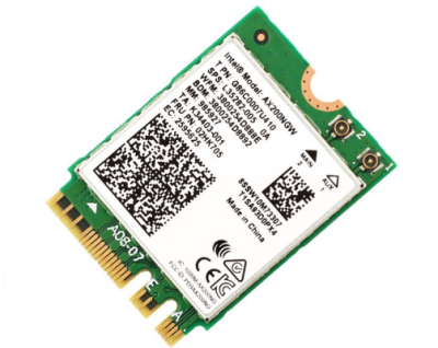 英特尔Wi-Fi 7新品BE213发布:三频160MHz频宽能否满足未来需求?

 苹果折叠屏iPhone重磅曝光:自研C2芯片+无痕屏幕或颠覆行业
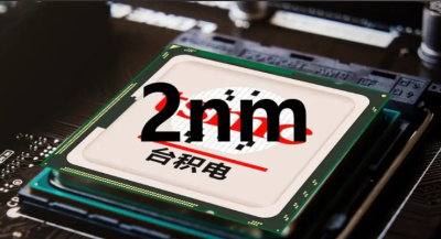 台积电2nm芯片生产全面停用中国设备 全球供应链加速重构
 英伟达暂停中国特供H20芯片生产:科技博弈下的市场困局
工作时间:9:00-21:00
CEO邮箱:ceo@jiepei.com
投诉邮箱:tousu@jiepei.com


 浙公网安备 33010502006866号 浙ICP备10014259号-119
营业执照ICP证
浙公网安备 33010502006866号 浙ICP备10014259号-119
营业执照ICP证


