
 5秒后页面跳转

| 型号 | 品牌 | 获取价格 | 描述 | 数据表 |
| AD8237 | ADI |
获取价格 |
Micropower, Zero Drift, True Rail-to-Rail Instrumentation Amplifier |

|
| AD8237ARMZ | ADI |
获取价格 |
Micropower, Zero Drift, True Rail-to-Rail Instrumentation Amplifier |
|
| AD8237ARMZ-R7 | ADI |
获取价格 |
Micropower, Zero Drift, True Rail-to-Rail Instrumentation Amplifier |
|
| AD8237ARMZ-RL | ADI |
获取价格 |
Micropower, Zero Drift, True Rail-to-Rail Instrumentation Amplifier |
|
| AD823A | ADI |
获取价格 |
Wide Supply Dual, 17 MHz, Rail-to-Rail |
|
| AD823A_12 | ADI |
获取价格 |
Wide Supply Dual, 17 MHz, Rail-to-Rail |
|
| AD823A-2AR-EBZ | ADI |
获取价格 |
Wide Supply Dual, 17 MHz, Rail-to-Rail |
|
| AD823A-2ARM-EBZ | ADI |
获取价格 |
Wide Supply Dual, 17 MHz, Rail-to-Rail |
|
| AD823AARMZ | ADI |
获取价格 |
Wide Supply Dual, 17 MHz, Rail-to-Rail |
|
| AD823AARMZ-R7 | ADI |
获取价格 |
Wide Supply Dual, 17 MHz, Rail-to-Rail |
|
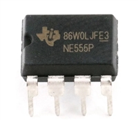 解读NE555P资料手册:电气参数、引脚功能及替换型号推荐

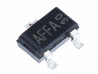 AO3415资料解读:电气参数、替换型号推荐
 电阻上的数字意义及电阻值辨别方法
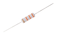 金属氧化膜电阻器:定义、特点与深入解读
工作时间:9:00-21:00
CEO邮箱:ceo@jiepei.com
投诉邮箱:tousu@jiepei.com


 浙公网安备 33010502006866号 浙ICP备10014259号-119
营业执照ICP证
浙公网安备 33010502006866号 浙ICP备10014259号-119
营业执照ICP证


