
 5秒后页面跳转

| 品牌 | Logo | 应用领域 |
| ANALOGICTECH | 开关 | |
| 页数 | 文件大小 | 规格书 |
| 13页 | 286K |  |
| 描述 | ||
| Over-Voltage Protection Switch | ||

| 型号 | 品牌 | 描述 | 获取价格 | 数据表 |
| AAT4684ITP-6.5-T1 | ANALOGICTECH | Over-Voltage Protection Switch |
获取价格 |
|
| AAT4684ITP-T1 | ANALOGICTECH | Over-Voltage Protection Switch |
获取价格 |
|
| AAT4685IWP-1-T1 | SKYWORKS | Buffer/Inverter Based Peripheral Driver |
获取价格 |
|
| AAT4685IWP-2-T1 | SKYWORKS | Buffer/Inverter Based Peripheral Driver |
获取价格 |
|
| AAT4685IWP-3-T1 | SKYWORKS | Buffer/Inverter Based Peripheral Driver |
获取价格 |
|
| AAT4686 | ANALOGICTECH | MOSFET Driver IC with Over-Voltage Protection |
获取价格 |
|
| AAT4686IJS-6.5-T1 | SKYWORKS | Buffer/Inverter Based MOSFET Driver |
获取价格 |
|
| AAT4686IJS-T1 | SKYWORKS | Buffer/Inverter Based MOSFET Driver, |
获取价格 |
|
| AAT4687-1IJQ-T1 | SKYWORKS | Interface Circuit, PDSO10, SC-70JW, 10 PIN |
获取价格 |
|
| AAT4687IJQ-1-T1 | SKYWORKS | Buffer/Inverter Based Peripheral Driver, |
获取价格 |
|
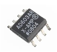 AD603资料手册解读:封装、引脚功能及电气参数全面分析

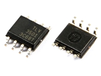 TLV3501高性能比较器详解:封装、引脚说明及替代型号推荐
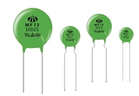 热敏电阻型号命名规则的深度解析
 晶闸管控制角与电压关系专业性解答
工作时间:9:00-21:00
CEO邮箱:ceo@jiepei.com
投诉邮箱:tousu@jiepei.com


 浙公网安备 33010502006866号 浙ICP备10014259号-119
营业执照ICP证
浙公网安备 33010502006866号 浙ICP备10014259号-119
营业执照ICP证


