Features
nꢀ Compliantꢀleadsꢀtoꢀreduceꢀsolderꢀjointꢀꢀ
fatiguing
nꢀ Standardꢀelectricalꢀschematics:ꢀisolated,ꢀꢀ
bussed,ꢀdualꢀterminator
nꢀ RoHSꢀcompliant*ꢀ(seeꢀHowꢀtoꢀOrderꢀꢀ
ꢀ
4
6
1
ꢀ “Termination”ꢀoption)
2
8
8
1
–
1
2
3
6
nꢀ StandardꢀEIAꢀpackageꢀcompatibleꢀwithꢀꢀ
automaticꢀplacementꢀequipment
P
C
ꢀ
L
ꢀ
F
nꢀ AEC-Q200ꢀcompliant
3
nꢀ Tapeꢀandꢀreelꢀpackagingꢀstandardꢀ
nꢀ Now available with improved tolerance to
±0.5 %
nꢀ Customꢀcircuitsꢀareꢀavailable
4800P Series - Thick Film Surface Mounted Medium Body
3312 - 2 mm SMD Trimming Potentiometer
Package Power Temp. Derating Curve
Additional Information
Product Characteristics
Resistance Range
Click these links for more information:
4820P
1.6
1.4
1.2
1.0
.8
.6
.4
.2
................... 10 ohms to 2.2 megohms
Maximum Operating Voltage...........50 V
Temperature Coefficient of Resistance
50 Ω and above..............±100 ppm/°C
below 50 Ω.....................±250 ppm/°C
TCR Tracking
4818P
4816P
4814P
PRODUCT TECHNICAL INVENTORY SAMPLES CONTACT
LIBRARY
(for equal values within a package)
.....50 ppm/°C max. for values > 50 Ω;
.............100 ppm/°C for values ≤ 50 Ω
Operating Temperature
................................-55 °C to +125 °C
Insulation Resistance
Product Dimensions
0
25
70
AMBIENT TEMPERATURE ( C )
125
5.59ꢀ±ꢀ.12
(.220ꢀ±ꢀ.005)
ϒ
........................ 10,000 megohms min.
Dielectric Withstanding Voltage
...........................................200 VRMS
Lead Solderability.....Meet requirements
of MIL-STD-202 Method 208
Package Power Rating at 70 °C
4814P.....................................1.12 watts
4816P.....................................1.28 watts
4818P.....................................1.44 watts
4820P.....................................1.60 watts
.432ꢀ ꢀ.076
TYP.
(.017ꢀ ꢀ.003)
7.62ꢀ±ꢀ.25
(.300ꢀ±ꢀ.010)
Environmental Characteristics
13.72ꢀ ꢀ.12
(.540ꢀ ꢀ.005)
12.45ꢀ ꢀ.12
(.490ꢀ ꢀ.005)
Typical Part Marking
TESTS PER MIL-STD-202...... ∆R MAX.
Short Time Overload..................±0.25 %
Load Life....................................±1.00 %
Moisture Resistance..................±0.50 %
Resistance to Soldering Heat....±0.25 %
Thermal Shock ..........................±0.25 %
11.18ꢀ ꢀ.12
(.440ꢀ ꢀ.005)
Represents total content. Layout may
vary.
9.91ꢀ ꢀ.12
(.390ꢀ ꢀ.005)
RoHSꢀCOMPLIANCY
PART
NUMBER
INDICATOR
1.27ꢀ ꢀ.076
(.050ꢀ ꢀ.003*)
RESISTANCEꢀCODE
CIRCUIT
4816P LF
2-682
TYP.
Physical Characteristics
CYYWW
.13ꢀ+ꢀ.12/ꢀ-ꢀ.00
(.005ꢀ+ꢀ.005/ꢀ-ꢀ.000)
PINꢀONE
INDICATOR
DATEꢀCODE
Flammability ........ Conforms to UL94V-0
Lead Frame Material
.........................Copper, solder coated
Body Material................... Thermoplastic
MANUFACTURER'S
TRADEMARK
COUNTRYꢀOFꢀMANUFACTURE
(Cꢀ=ꢀCOSTAꢀRICA)
2.03ꢀ ꢀ.12
(.080ꢀ ꢀ.005)
.305ꢀ+ꢀ.000/ꢀ-ꢀ.101
(.012ꢀ+ꢀ.000/ꢀ-ꢀ.004)
Rꢀ=ꢀ.008"ꢀTYP.
Recommended Land Pattern
How To Order
2.0
(.079)
8°ꢀMAX.
.611ꢀ ꢀ.101
(.024ꢀ ꢀ.004)
TYP.
48 16 P - 1 - 103 __ __
1
2
3
4
5
6
7
8
9
20
19
18
17
16
15
14
13
12
Model
(48 = SOM Pkg.)
Number of Pins
Electrical Configuration
• 1 or 4 = Isolated*
• 2 = Bussed*
• 3 = Dual Terminator*
Resistance Code
SOM-14
8.26
(.325)
1.27
(.050)
TYP.
TYP.
SOM-16
9.53
(.375)
SOM-18
10.80
(.425)
Leadꢀcoplanarityꢀ.102mmꢀ(.004ꢀinch)ꢀmax.ꢀatꢀmountingꢀsurface.
SOM-20
12.07
(.475)
Governingꢀdimensionsꢀareꢀinꢀmetric.ꢀDimensionsꢀinꢀparenthesesꢀ
areꢀinchesꢀandꢀareꢀapproximate.
.63
(.025)
ꢀ
10 11
*Terminalꢀcenterlineꢀtoꢀcenterlineꢀmeasurementsꢀmadeꢀatꢀpointꢀof
emergenceꢀofꢀtheꢀleadꢀfromꢀtheꢀbody.
4.9
(.193)
• First 2 digits are significant
• Third digit represents the
number of zeros to follow.
8.9
(.350)
NOTE: Land pattern dimensions are based on
design rules established by the Institute for Inter-
connecting and Packaging Electronic Circuits in
IPC-SM-782.
Resistance Tolerance
• Blank = ±2 % (see “Resistance Tolerance”
on next page for resistance range)
• F = ±1 % (100 ohms - 1 megohm)
• D = ±0.5 % (100 ohms - 1 megohm)
Terminations
• All electrical configurations EXCEPT T03:
LF = RoHS compliant
• ONLY electrical configuration T03:
L = RoHS compliant
• Blank = Tin/Lead-plated
For Standard Values Used in
Capacitors, Inductors, and Resistors,
click here.
*For tube packaging, use T01, T02, T03 or T04.
Consult factory for other available options.
WARNING Cancer and Reproductive Harm
www.P65Warnings.ca.gov
*RoHSꢀDirectiveꢀ2015/863,ꢀMarꢀ31,ꢀ2015ꢀandꢀAnnex.ꢀ
Specificationsꢀareꢀsubjectꢀtoꢀchangeꢀwithoutꢀnotice.
Usersꢀshouldꢀverifyꢀactualꢀdeviceꢀperformanceꢀinꢀtheirꢀspecificꢀapplications.ꢀ
Theꢀproductsꢀdescribedꢀhereinꢀandꢀthisꢀdocumentꢀareꢀsubjectꢀtoꢀspecificꢀlegalꢀdisclaimersꢀasꢀsetꢀforthꢀonꢀtheꢀlastꢀpageꢀofꢀthisꢀdocument,ꢀandꢀatꢀwww.bourns.com/docs/legal/disclaimer.pdf.


 国产x86处理器里程碑!兆芯6000台医疗电脑中标某总医院

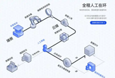 稚晖君团队开源GO-1模型:ViLLA架构如何重塑具身智能未来?
 安森美收购奥拉半导体Vcore技术 抢占AI数据中心电源管理制高点
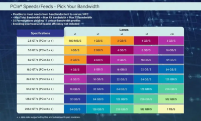 PCIe 8.0规范草案获里程碑进展:256GT/s速率开启1TB/s带宽时代


 浙公网安备 33010502006866号 浙ICP备10014259号-119
营业执照ICP证
浙公网安备 33010502006866号 浙ICP备10014259号-119
营业执照ICP证


