
 5秒后页面跳转

| 型号 | 品牌 | 获取价格 | 描述 | 数据表 |
| 20IMX7-03-7 | BEL |
获取价格 |
DC-DC Regulated Power Supply Module, 1 Output, 6W, Hybrid |

|
| 20IMX7-03-7C | BEL |
获取价格 |
DC-DC Regulated Power Supply Module, 1 Output, 5W, Hybrid, 2 X 1 INCH, 10.50 MM HEIGHT, MA |
|
| 20IMX7-03-7D | BEL |
获取价格 |
DC-DC Regulated Power Supply Module, 1 Output, 6W, Hybrid |
|
| 20IMX7-03-7DC | BEL |
获取价格 |
DC-DC Regulated Power Supply Module, 1 Output, 5W |
|
| 20IMX7-03-8 | BEL |
获取价格 |
7-Watt DC-DC Converters |
|
| 20IMX7-03-8 | POWER-ONE |
获取价格 |
IMX7/IMS7 DC-DC Series Data Sheet 7-Watt DC-DC Converters |
|
| 20IMX7-03-8D | BEL |
获取价格 |
DC-DC Regulated Power Supply Module, 1 Output, 7W, Hybrid, |
|
| 20IMX7-03-8DL | BEL |
获取价格 |
DC-DC Regulated Power Supply Module, 1 Output, 7W, Hybrid |
|
| 20IMX7-03-8DM | BEL |
获取价格 |
DC-DC Regulated Power Supply Module, 1 Output, 7W, Hybrid, |
|
| 20IMX7-03-8DZ | BEL |
获取价格 |
DC-DC Regulated Power Supply Module, 1 Output, 7W, Hybrid, |
|
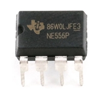 解读NE555P资料手册:电气参数、引脚功能及替换型号推荐

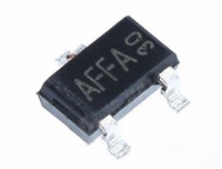 AO3415资料解读:电气参数、替换型号推荐
 电阻上的数字意义及电阻值辨别方法
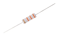 金属氧化膜电阻器:定义、特点与深入解读
工作时间:9:00-21:00
CEO邮箱:ceo@jiepei.com
投诉邮箱:tousu@jiepei.com


 浙公网安备 33010502006866号 浙ICP备10014259号-119
营业执照ICP证
浙公网安备 33010502006866号 浙ICP备10014259号-119
营业执照ICP证


