SINGLE OUTPUT HIGH VOLTAGE MODULES
16
10A-25A SERIES
10kV to 25kV High Voltage Biasing Supplies
The 10A-25A Series of regulated, high-voltage DC-DC converters are
an extension of the A Series, directly addressing the needs of the
miniature PCB or chassis-mount ≥10kV application. Designed and
built utilizing state-of-the-art power conversion topology, these units
feature surface-mount technology and encapsulation techniques
providing high reliability and low cost. Typical applications for
the 10A-25A Series include the following: electrophoresis, mass
spectroscopy, electron microscopes, plasma and cathode ray tubes
(CRT).
• Output current & voltage monitors
• Fixed-frequency, low-stored-energy design
• >450,000 hour MTBF @65°C
• 0 to 10kV, 15kV, 20kV, or 25kV output
• 4, 15 or 30 watts of output power
• Maximum Iout capability down to 0 Volts
• Wide input voltage range
• UL/cUL Recognized Component; CE Mark (LVD & RoHS)
• Indefinite output short-circuit protection
PARAMETER
CONDITIONS
MODELS
UNITS
INPUT
Voltage Range
Voltage Range
Current
12V
24V
Full Power
+ 11 to 16
+ 23 to 30
VDC
VDC
mA
Derated Power Range
Standby / Disable
+ 9 to 32
+ 9 to 32
< 30
< 30
Current
No Load, Max Eout
10A < 0.20, 15A/20A/25A < 0.25
10A < 0.17, 15A < 0.20, 20A < 0.21, 25A < 0.25
A
Current
Max Load, Max Eout
Nominal Input, Full Load
~ 500
< 80
~ 1600
< 80
mA
AC Ripple Current
mA p-p
OUTPUT
Voltage Range
10A
15A
0 to 15,000
24
20A
0 to 20,000
24
25A
0 to 25,000
24
Nominal Input
0 to 10,000
VDC
VDC
Nominal Input Voltage
Power
12
4
24
15
24
30
12
4
24
30
12
4
24
30
12
4
24
30
Nominal Input, Max Eout
Iout Entire Output Voltage Range
Full Load
15
15
15
Watts
mA
0.26
0.158
Current
0.40
0.167
1.5
3.0
1.0
2.0
0.20
0.152
0.75
1.5
0.16
0.145
0.60
1.2
Current Scale Factor
Voltage Monitor Scaling
Ripple
0.184
0.381
0.181
0.378
0.178
0.184
0.175
0.183
mA/V
-
1000:1 2ꢀ into 10Mꢁ
Full Load, Max Eout, 300pF bypass Cap.
Full Load, Max Eout, 300pF bypass Cap.
½ to Full Load, Max Eout per 0.1mA
Nom. Input, Max Eout, Full Power
No Load to Full Load, Max Eout
0.012
0.008
<5.0
0.039
0.034
<5.0
0.076
0.072
<5.0
0.024
0.021
<7.5
0.043
0.028
<7.5
0.080
0.073
<7.5
0.020
0.010
<10.0
0.031
0.018
<10.0
0.080
0.039
<10.0
0.020
0.010
<10.0
0.080
0.040
<10.0
0.051
0.040
<10.0
ꢀV p-p
ꢀV p-p
V pk
VDC
Ripple with -F-M Option
Dynamic Load Regulation
Line Regulation
Static Load Regulation
Stability
< 0.01 ꢀ
< 0.01ꢀ
VDC
30 Min. warmup, per 8 hr/ per day
< 0.01ꢀ / < 0.02ꢀ
VDC
PROGRAMMING & CONTROLS
ALL TYPES
Input Impedance
Adjust Resistance
Adjust Logic
Nominal Input
+ Output Models 1.1MΩ to GND, - Output Models 1.1MΩ to +5 Vref
10K to 100K (Pot across Vref. & Signal GND, Wiper to Adjust)
+4.64 VDC for +Output or +0.36 for -Output = Nominal Eout
+ 5.00VDC 2ꢀ, ꢂout = 464Ω 1ꢀ
MΩ
Ω
Typical Potentiometer Values
0 to +5 for +Out, +5 to 0 for - Out
T=+25°C
-
Output Voltage & Impedance
Enable/Disable
-
0 to +0.5 Disable, +2.4 to 32 Enable (Default = Enable)
VDC
ENVIRONMENTAL
Operating
STANDARD
-25PPM
Full Load, Max Eout, Case Temp.
Over the Specified Temperature
Mil-Std 810, Method 503-4, Proc. II
Non-Operating, Case Temp.
-40 to +65
+10 to +45
°C
PPM/°C
°C
Coefficient
Thermal Shock
Storage
50
25
-40 to +65
-55 to +105
°C
Humidity
All Conditions, Standard Package
Standard Package, All Conditions
Mil-Std-810, Method 516.5, Proc. IV
Mil-Std-810, Method 514.5, Fig.514.5C-3
0 to 95ꢀ non-condensing
-
Altitude
Sea Level through Vacuum (Vacuum may require -P2 option, contact factory for details.)
20 (Standard), 40 (-C Option)
-
Shock
G’s
G’s
Vibration
10 (Standard), 20 (-C Option)
Specifications subject to change without notice.
Higher Service, Higher Performance, Higher Reliability
Making High Voltage Easier!®
©2011, UltraVolt Inc. All rights reserved.
ULT
LT
®


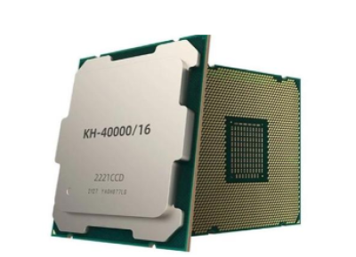 国产x86处理器里程碑!兆芯6000台医疗电脑中标某总医院

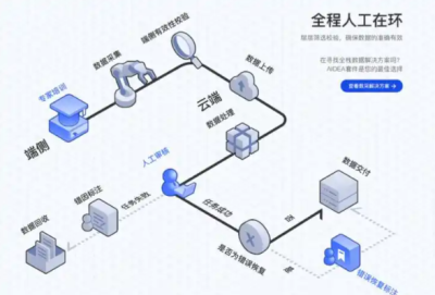 稚晖君团队开源GO-1模型:ViLLA架构如何重塑具身智能未来?
 安森美收购奥拉半导体Vcore技术 抢占AI数据中心电源管理制高点
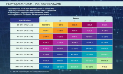 PCIe 8.0规范草案获里程碑进展:256GT/s速率开启1TB/s带宽时代


 浙公网安备 33010502006866号 浙ICP备10014259号-119
营业执照ICP证
浙公网安备 33010502006866号 浙ICP备10014259号-119
营业执照ICP证


