
 5秒后页面跳转

| 型号 | 品牌 | 描述 | 获取价格 | 数据表 |
| ULN-2003A | ETC | Septuple Peripheral Driver |
获取价格 |

|
| ULN2003AC | HGSEMI | 7通道达林顿晶体管阵列 |
获取价格 |
|
| ULN2003AD | TI | HIGH-VOLTAGE HIGH-CURRENT DARLINGTON TRANSISTOR ARRAY |
获取价格 |
|
| ULN2003AD-00R | TI | 50V, 7 CHANNEL, NPN, Si, SMALL SIGNAL TRANSISTOR |
获取价格 |
|
| ULN2003AD16-U | DIODES | Power Bipolar Transistor, |
获取价格 |
|
| ULN2003ADE4 | TI | HIGH-VOLTAGE HIGH-CURRENT DARLINGTON TRANSISTOR ARRAY |
获取价格 |
|
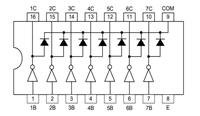 ULN2003A引脚图及功能介绍

 ULN2003A的资料手册参数解读和应用示例分享
 pcf8563芯片功能说明、参数分析、引脚说明
 TDA2822资料手册:引脚说明、参数分析
工作时间:9:00-21:00
CEO邮箱:ceo@jiepei.com
投诉邮箱:tousu@jiepei.com


 浙公网安备 33010502006866号 浙ICP备10014259号-119
营业执照ICP证
浙公网安备 33010502006866号 浙ICP备10014259号-119
营业执照ICP证


