
 5秒后页面跳转

| 生命周期: | Obsolete | Reach Compliance Code: | unknown |
| ECCN代码: | EAR99 | HTS代码: | 8504.50.80.00 |
| 风险等级: | 5.84 | 电感器类型: | GENERAL PURPOSE INDUCTOR |
| Base Number Matches: | 1 |
| 型号 | 品牌 | 获取价格 | 描述 | 数据表 |
| ST450RAA332JLZ | COILCRAFT |
获取价格 |
Chip Inductors for Critical Applications |

|
| ST450RAA392_LZ | COILCRAFT |
获取价格 |
Chip Inductors for Critical Applications |
|
| ST450RAA472JLZ | COILCRAFT |
获取价格 |
Chip Inductors for Critical Applications |
|
| ST450RAA562JQH | COILCRAFT |
获取价格 |
General Purpose Inductor, 5.6uH, 5%, 1 Element, Ceramic-Core, SMD, 2015, CHIP, 2015, ROHS |
|
| ST450RAB | COILCRAFT |
获取价格 |
Chip Inductors for Critical Applications |
|
| ST450RAB104JLZ | COILCRAFT |
获取价格 |
Chip Inductors for Critical Applications |
|
| ST450RAB105JLZ | COILCRAFT |
获取价格 |
Chip Inductors for Critical Applications |
|
| ST450RAB105JQZ | COILCRAFT |
获取价格 |
General Purpose Inductor, 1000uH, 5%, Ferrite-Core, 1915 |
|
| ST450RAB123JLZ | COILCRAFT |
获取价格 |
Chip Inductors for Critical Applications |
|
| ST450RAB124JLZ | COILCRAFT |
获取价格 |
Chip Inductors for Critical Applications |
|
 Pickering新高压舌簧继电器亮相汽车测试博览会

 采用MCU+MPU双处理器架构实现的创新应用设计探索
 解读L9904TR手册资料:产品概述、主要功能、电气参数
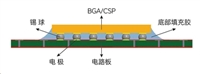 芯片底部填充工艺:提升电子设备可靠性的关键步骤
工作时间:9:00-21:00
CEO邮箱:ceo@jiepei.com
投诉邮箱:tousu@jiepei.com


 浙公网安备 33010502006866号 浙ICP备10014259号-119
营业执照ICP证
浙公网安备 33010502006866号 浙ICP备10014259号-119
营业执照ICP证


