
 5秒后页面跳转

| 生命周期: | Obsolete | 包装说明: | QFP-100 |
| Reach Compliance Code: | unknown | 风险等级: | 5.83 |
| 具有ADC: | YES | 地址总线宽度: | 16 |
| 位大小: | 16 | 最大时钟频率: | 30 MHz |
| DAC 通道: | NO | DMA 通道: | YES |
| JESD-30 代码: | S-PQFP-G100 | I/O 线路数量: | 40 |
| 端子数量: | 100 | 最高工作温度: | 70 °C |
| 最低工作温度: | -20 °C | PWM 通道: | YES |
| 封装主体材料: | PLASTIC/EPOXY | 封装代码: | QFP |
| 封装形状: | SQUARE | 封装形式: | FLATPACK |
| 认证状态: | Not Qualified | 最大供电电压: | 5.5 V |
| 最小供电电压: | 4.5 V | 标称供电电压: | 5 V |
| 表面贴装: | YES | 技术: | CMOS |
| 温度等级: | COMMERCIAL | 端子形式: | GULL WING |
| 端子位置: | QUAD | uPs/uCs/外围集成电路类型: | MICROCONTROLLER |
| Base Number Matches: | 1 |
| 型号 | 品牌 | 描述 | 获取价格 | 数据表 |
| SM6011 | NPC | High-speed Data Converter |
获取价格 |

|
| SM6018NSU | SINOPWER | N-Channel Enhancement Mode MOSFET |
获取价格 |
|
| SM6018NSUB | SINOPWER | N-Channel Enhancement Mode MOSFET |
获取价格 |
|
| SM6018NSUBC-TUG | SINOPWER | N-Channel Enhancement Mode MOSFET |
获取价格 |
|
| SM6018NSUC-TRG | SINOPWER | N-Channel Enhancement Mode MOSFET |
获取价格 |
|
| SM601BA10A1 | EATON | Remote Controlled Circuit Breaker (RCCB) |
获取价格 |
|
 AD620资料手册解读:引脚说明及功能介绍、参数分析

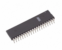 AT89C52资料手册:引脚说明、参数解读、LED流水灯控制程序示例
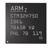 STM32H750IB资料手册解读:参数分析、引脚说明、应用示例介绍
 SG3525资料手册详解:SG3525参数分析、引脚说明、应用介绍
工作时间:9:00-21:00
CEO邮箱:ceo@jiepei.com
投诉邮箱:tousu@jiepei.com


 浙公网安备 33010502006866号 浙ICP备10014259号-119
营业执照ICP证
浙公网安备 33010502006866号 浙ICP备10014259号-119
营业执照ICP证


