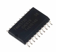
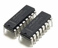
| 是否无铅: | 不含铅 | 是否Rohs认证: | 符合 |
| 生命周期: | Active | 零件包装代码: | QFN |
| 包装说明: | QFN-16 | 针数: | 16 |
| Reach Compliance Code: | compliant | ECCN代码: | EAR99 |
| HTS代码: | 8542.39.00.01 | Factory Lead Time: | 1 week |
| 风险等级: | 0.82 | Is Samacsys: | N |
| 最大时钟频率: | 0.4 MHz | JESD-30 代码: | S-PQCC-N16 |
| JESD-609代码: | e4 | 长度: | 4 mm |
| 湿度敏感等级: | 2 | 位数: | 8 |
| I/O 线路数量: | 8 | 端口数量: | 1 |
| 端子数量: | 16 | 最高工作温度: | 85 °C |
| 最低工作温度: | -40 °C | 封装主体材料: | PLASTIC/EPOXY |
| 封装代码: | HVQCCN | 封装等效代码: | LCC16,.16SQ,25 |
| 封装形状: | SQUARE | 封装形式: | CHIP CARRIER, HEAT SINK/SLUG, VERY THIN PROFILE |
| 峰值回流温度(摄氏度): | 260 | 电源: | 2.5/5 V |
| 认证状态: | Not Qualified | 座面最大高度: | 1 mm |
| 子类别: | Parallel IO Ports | 最大压摆率: | 0.175 mA |
| 最大供电电压: | 5.5 V | 最小供电电压: | 2.3 V |
| 标称供电电压: | 5 V | 表面贴装: | YES |
| 技术: | CMOS | 温度等级: | INDUSTRIAL |
| 端子面层: | Nickel/Palladium/Gold (Ni/Pd/Au) | 端子形式: | NO LEAD |
| 端子节距: | 0.65 mm | 端子位置: | QUAD |
| 处于峰值回流温度下的最长时间: | NOT SPECIFIED | 宽度: | 4 mm |
| uPs/uCs/外围集成电路类型: | PARALLEL IO PORT, GENERAL PURPOSE | Base Number Matches: | 1 |
| 型号 | 品牌 | 描述 | 获取价格 | 数据表 |
| PCA9534PW,112 | NXP | PCA9534 - 8-bit I2C-bus and SMBus low power I/O port with interrupt TSSOP 16-Pin |
获取价格 |

|
| PCA9534PW/DG,118 | NXP | PCA9534 - 8-bit I2C-bus and SMBus low power I/O port with interrupt TSSOP 16-Pin |
获取价格 |

|
| PCA9534PWG4 | TI | REMOTE 8-BIT I2C AND SMBus LOW-POWER I/O EXPANDER WITH INTERRUPT OUTPUT AND CONFIGURATION |
获取价格 |

|
| PCA9534PWR | TI | REMOTE 8-BIT I2C AND SMBus LOW-POWER I/O EXPANDER WITH INTERRUPT OUTPUT AND CONFIGURATION |
获取价格 |

|
| PCA9534PWRG4 | TI | REMOTE 8-BIT I2C AND SMBus LOW-POWER I/O EXPANDER WITH INTERRUPT OUTPUT AND CONFIGURATION |
获取价格 |

|
| PCA9534PWT | TI | IC 8 I/O, PIA-GENERAL PURPOSE, PDSO16, PLASTIC, TSSOP-16, Parallel IO Port |
获取价格 |

|
 一文带你了解ss8050参数、引脚配置、应用指南

 深入解析AD7606高性能多通道模数转换器:资料手册参数分析

 74HC573三态非易失锁存器(Latch)资料手册参数分析

 MAX3232 RS-232电平转换器资料手册参数分析
