
 5秒后页面跳转

| 型号 | 品牌 | 获取价格 | 描述 | 数据表 |
| LTC6602CUF-PBF | Linear |
获取价格 |
Dual Matched, High Frequency Bandpass/Lowpass Filters |

|
| LTC6602CUF-TRPBF | Linear |
获取价格 |
Dual Matched, High Frequency Bandpass/Lowpass Filters |
|
| LTC6602IUF-PBF | Linear |
获取价格 |
Dual Matched, High Frequency Bandpass/Lowpass Filters |
|
| LTC6602IUF-TRPBF | Linear |
获取价格 |
Dual Matched, High Frequency Bandpass/Lowpass Filters |
|
| LTC6603 | Linear |
获取价格 |
Dual Adjustable Lowpass Filter |
|
| LTC6603 | ADI |
获取价格 |
双通道、可调低通滤波器 |
|
| LTC6603CUF#PBF | Linear |
获取价格 |
LTC6603 - Dual Adjustable Lowpass Filter; Package: QFN; Pins: 24; Temperature Range: 0& |
|
| LTC6603CUF-PBF | Linear |
获取价格 |
Dual Adjustable Lowpass Filter |
|
| LTC6603CUF-TRPBF | Linear |
获取价格 |
Dual Adjustable Lowpass Filter |
|
| LTC6603IUF-PBF | Linear |
获取价格 |
Dual Adjustable Lowpass Filter |
|
 Pickering新高压舌簧继电器亮相汽车测试博览会

 采用MCU+MPU双处理器架构实现的创新应用设计探索
 解读L9904TR手册资料:产品概述、主要功能、电气参数
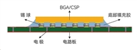 芯片底部填充工艺:提升电子设备可靠性的关键步骤
工作时间:9:00-21:00
CEO邮箱:ceo@jiepei.com
投诉邮箱:tousu@jiepei.com


 浙公网安备 33010502006866号 浙ICP备10014259号-119
营业执照ICP证
浙公网安备 33010502006866号 浙ICP备10014259号-119
营业执照ICP证


