Document 409
For Maxim MAX5941A
Flyback Transformer PoE Interface/PWM Controller
•ꢀDesigned for IEEE 802.3af-compliant PoE applications
•ꢀOperates with 32–56 Volts input
•ꢀ1500 Vrms, one minute isolation between the primary and the
secondary
Core material Ferrite
Terminations RoHS tin-silver over tin over nickel over phos bronze.
Other terminations available at additional cost.
Weight 5.7 g
Ambient temperature –40°C to +125°C
Storage temperature Component: –40°C to +125°C.
Tape and reel packaging: –40°C to +80°C
Resistance to soldering heat Max three 40 second reflows at
+260°C, parts cooled to room temperature between cycles
Moisture Sensitivity Level (MSL) 1 (unlimited floor life at <30°C /
85% relative humidity)
Failures in Time (FIT) / Mean Time Between Failures (MTBF)
38 per billion hours / 26,315,789 hours, calculated per Telcordia SR-332
Packaging 200 per 13″ reel Plastic tape: 44 mm wide,
0.37 mm thick, 28 mm pocket spacing, 9.0 mm pocket depth
PCB washing Tested with pure water or alcohol only. For other solvents,
see Doc787_PCB_Washing.pdf.
Inductance
at0A2
Inductance
at Ipk3
Leakage
inductance5
max (µH)
DCR max (Ohms)4
pri sec bias
0.283 0.013 0.480
Turns ratio6
pri:sec pri:bias
Part
Ipk3
number1
±±5(µH)
min (µH)
(A)
Output7
C1099-AL_
133.0
126.0
3.5
1:0.13
1:0.57
0.9 3.3V, 2.5A
1. When ordering, please specify packaging code:
C1099-ALD
4. Primary DCR is measured with the windings connected in series. Sec-
ondary DCR is measured with the windings connected in parallel.
5. Leakage inductance is for the primary winding with the secondary wind-
ing shorted.
6. Turns ratio is for the primary connected in series and the secondary con-
nected in parallel.
Packaging: D = 13″ machine ready reel. EIA-481 embossed plastic
tape (200 per full reel).
B = Less than full reel. In tape, but not machine ready.
To have a leader and trailer added ($25 charge), use
code letter D instead.
7. Output of the secondary is with the windings connected in parallel. Bias
winding output is 14 V.
8. Electrical specifications at 25°C.
Refer to Doc 362 “Soldering Surface Mount Components” before soldering.
2. Inductance is for the primary, measured at 300 kHz, 1.0 Vrms.
3. Peak primary current drawn at minimum input voltage.
8
Dot indicates pin 1
7
1
1
12
12
7
1
6
C1099-AL
XXXXY
Secondary
½ Primary
0.677
17,20
max
max
6
5
0.098
2,5
0.098
2,5
12
0.028
0,72
11
0.135
3,43
0.665
16,88
Recommended
Land Pattern
0.865
max
0.07
1,79
½ Primary
21,97
2
0.335
8,51
10
0.004/0,10
0.590
14,98
0.693
17,60
Bias
0.079
2,01
3
inches
mm
Dimensions are in
Primary windings to be connected in series and
secondary windings to be connected in parallel
on the PC board.
Document 409 Revised 10/28/08
US +1-847-639-6400 sales@coilcraft.com
UK +44-1236-730595 sales@coilcraft-europe.com
Taiwan +886-2-2264 3646 sales@coilcraft.com.tw
China +86-21-6218 8074 sales@coilcraft.com.cn
Singapore + 65-6484 8412 sales@coilcraft.com.sg
© Coilcraft Inc. 2013
This product may not be used in medical or high
risk applications without prior Coilcraft approval.
Specification subject to change without notice.
Please check web site for latest information.

 5秒后页面跳转


 NE5532双低噪声运算放大器:资料手册参数分析

 74LS138 3-to-8线解码器/多路复用器:资料手册参数分析
 TDA2030音频功率放大器:资料手册参数分析
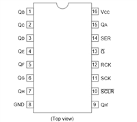 74HC595移位寄存器芯片:参数深入解析与应用实践指南


 浙公网安备 33010502006866号 浙ICP备10014259号-119
营业执照ICP证
浙公网安备 33010502006866号 浙ICP备10014259号-119
营业执照ICP证


