
 5秒后页面跳转

| 是否无铅: | 不含铅 | 是否Rohs认证: | 符合 |
| 生命周期: | Active | 包装说明: | , |
| Reach Compliance Code: | compliant | ECCN代码: | EAR99 |
| HTS代码: | 8532.22.00 | 风险等级: | 1.16 |
| 电容: | 560 µF | 电容器类型: | ALUMINUM ELECTROLYTIC CAPACITOR |
| 直径: | 8 mm | 介电材料: | ALUMINUM (SOLID POLYMER) |
| ESR: | 7 m Ω | JESD-609代码: | e4 |
| 漏电流: | 0.448 mA | 长度: | 9 mm |
| 安装特点: | THROUGH HOLE MOUNT | 负容差: | 20% |
| 端子数量: | 2 | 最高工作温度: | 105 °C |
| 最低工作温度: | -55 °C | 封装形状: | CYLINDRICAL PACKAGE |
| 封装形式: | Radial | 包装方法: | TAPE |
| 极性: | POLARIZED | 正容差: | 20% |
| 额定(直流)电压(URdc): | 4 V | 纹波电流: | 5200 mA |
| 系列: | LF | 表面贴装: | NO |
| Delta切线: | 0.08 | 端子面层: | Silver (Ag) |
| 端子节距: | 3.5 mm | 端子形状: | WIRE |
| Base Number Matches: | 1 |
| 型号 | 品牌 | 描述 | 获取价格 | 数据表 |
| PLF0G561MCO6TD | NICHICON | Aluminum Electrolytic Capacitor, Polarized, Aluminum (solid Polymer), 4V, 20% +Tol, 20% -T |
获取价格 |

|
| PLF0G561MDL1TD | NICHICON | Aluminum Electrolytic Capacitor, Polarized, Aluminum (solid Polymer), 4V, 20% +Tol, 20% -T |
获取价格 |
|
| PLF0G561MDO1 | NICHICON | CONDUCTIVE POLYMER ALUMINUM SOLID ELECTROLYTIC CAPACITORS |
获取价格 |
|
| PLF0G561MDO1_15 | NICHICON | CONDUCTIVE POLYMER ALUMINUM SOLID ELECTROLYTIC CAPACITORS |
获取价格 |
|
| PLF0G561MDO1TD | NICHICON | Aluminum Electrolytic Capacitor, Polarized, Aluminum (solid Polymer), 4V, 20% +Tol, 20% -T |
获取价格 |
|
| PLF0G681MDL1TD | NICHICON | Aluminum Electrolytic Capacitor, Polarized, Aluminum (solid Polymer), 4V, 20% +Tol, 20% -T |
获取价格 |
|
 TJA1050资料数据分析、引脚说明、应用示例介绍

 DS3231时钟芯片:参数分析、引脚说明、应用示例介绍
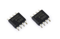 AD620资料手册解读:引脚说明及功能介绍、参数分析
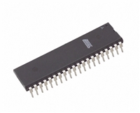 AT89C52资料手册:引脚说明、参数解读、LED流水灯控制程序示例
工作时间:9:00-21:00
CEO邮箱:ceo@jiepei.com
投诉邮箱:tousu@jiepei.com


 浙公网安备 33010502006866号 浙ICP备10014259号-119
营业执照ICP证
浙公网安备 33010502006866号 浙ICP备10014259号-119
营业执照ICP证


