
 5秒后页面跳转

| 型号 | 品牌 | 获取价格 | 描述 | 数据表 |
| PDR3G-13 | DIODES |
获取价格 |
3A GLASS PASSIVATED RECTIFIER |

|
| PDR54450QDDARQ1 | TI |
获取价格 |
汽车级 5.5V 至 36V 输入、5A、500kHz 降压转换器 | DDA | 8 | |
|
| PDR5G | DIODES |
获取价格 |
5A GLASS PASSIVATED RECTIFIER |
|
| PDR5G_1 | DIODES |
获取价格 |
5A GLASS PASSIVATED RECTIFIER |
|
| PDR5G-13 | DIODES |
获取价格 |
5A GLASS PASSIVATED RECTIFIER |
|
| PDR5K | DIODES |
获取价格 |
PDR5K - Industry first 5A/750V rectifier in a PowerDi-5 package |
|
| PDR5K-13 | DIODES |
获取价格 |
Rectifier Diode, 1 Phase, 1 Element, 5A, 750V V(RRM), Silicon, GREEN, PLASTIC PACKAGE-3 |
|
| PDR5KF-13 | DIODES |
获取价格 |
Rectifier Diode, 1 Phase, 1 Element, 5A, 800V V(RRM), Silicon, |
|
| PDR7.5102J250L4BULK | KEMET |
获取价格 |
Film Capacitor, Polypropylene, 250V, 5% +Tol, 5% -Tol, 0.001uF, Through Hole Mount, RADIAL |
|
| PDR7.5102J400L4BULK | KEMET |
获取价格 |
Film Capacitor, Polypropylene, 400V, 5% +Tol, 5% -Tol, 0.001uF, Through Hole Mount, RADIAL |
|
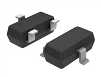 BSS123LT1资料解读:电气参数及替代型号推荐

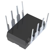 LTC1151C双通道±15V零漂移运算放大器全面解读
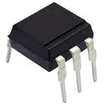 CNX36手册解读:产品特性、应用及封装引脚详解
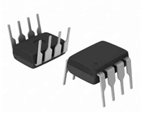 PS9552资料解读:引脚信息、电气参数
工作时间:9:00-21:00
CEO邮箱:ceo@jiepei.com
投诉邮箱:tousu@jiepei.com


 浙公网安备 33010502006866号 浙ICP备10014259号-119
营业执照ICP证
浙公网安备 33010502006866号 浙ICP备10014259号-119
营业执照ICP证


