
 5秒后页面跳转

| 型号 | 品牌 | 获取价格 | 描述 | 数据表 |
| ESDS302 | TI |
获取价格 |
适用于 USB 和以太网且具有 12A 8/20us 浪涌额定值的双路 4.5pF、3.6 |

|
| ESDS302DBVR | TI |
获取价格 |
适用于 USB 和以太网且具有 12A 8/20us 浪涌额定值的双路 4.5pF、3.6 |
|
| ESDS304 | TI |
获取价格 |
适用于 USB 和以太网且具有 12A 8/20us 浪涌额定值的四路 2.3pF、3.6 |
|
| ESDS304DBVR | TI |
获取价格 |
适用于 USB 和以太网且具有 12A 8/20us 浪涌额定值的四路 2.3pF、3.6 |
|
| ESDS311 | TI |
获取价格 |
采用 SOD-323 和 SOD-523 封装并用于 3.3V 浪涌保护的单通道单向器件 |
|
| ESDS311DYFR | TI |
获取价格 |
采用 SOD-323 和 SOD-523 封装并用于 3.3V 浪涌保护的单通道单向器件 |
|
| ESDS312 | TI |
获取价格 |
适用于 USB 和以太网且具有 25A 8/20us 浪涌额定值的双路 4.5pF、3.6 |
|
| ESDS312DBVR | TI |
获取价格 |
适用于 USB 和以太网且具有 25A 8/20us 浪涌额定值的双路 4.5pF、3.6 |
|
| ESDS314 | TI |
获取价格 |
适用于 USB 和以太网且具有 25A 8/20us 浪涌额定值的四路 4.5pF、3.6 |
|
| ESDS314DBVR | TI |
获取价格 |
适用于 USB 和以太网且具有 25A 8/20us 浪涌额定值的四路 4.5pF、3.6 |
|
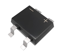 数据手册解读:MB10S引脚说明、电气参数

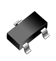 2N7002K资料解读:产品特性和型号推荐
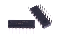 资料解读:TL494CN参数和引脚功能图说明
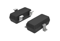 解读BAT54A数据手册:全面解析产品特性与应用
工作时间:9:00-21:00
CEO邮箱:ceo@jiepei.com
投诉邮箱:tousu@jiepei.com


 浙公网安备 33010502006866号 浙ICP备10014259号-119
营业执照ICP证
浙公网安备 33010502006866号 浙ICP备10014259号-119
营业执照ICP证


